Introduction:
The batteries of electric vehicles or plug-in hybrids can be charged with external charging facilities. The car can be connected with a charging cable to a public charging station, public charge point, or a personal wallbox (on the exterior wall or in the garage) to charge the battery through the power grid. There is often also a mobile charger available for charging via an outlet, though it is recommended to use this charger only in emergencies.
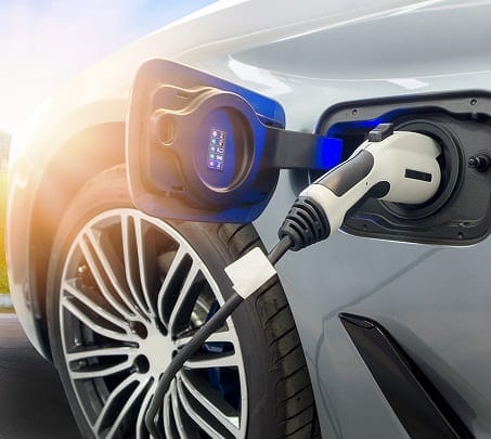
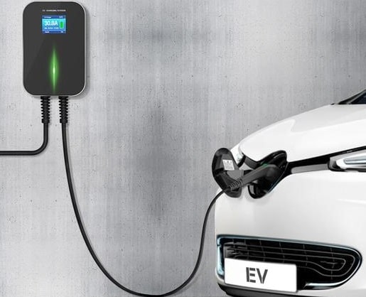
The following image shows the charging of an electric car. On the side of the vehicle, there is a flap that resembles a fuel cap of a traditional combustion engine car. Behind the flap is the socket where the charging plug can be inserted.
The sticker in the flap indicates which color the LED next to the plug will light up to indicate a certain status.

Charging Connectors and Connections:
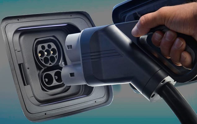
The charging connectors and connections are standardized in Europe. For AC charging (alternating current), we use the Mennekes (type 2), and for DC charging (direct current), the CCS2 plug.
The following image shows a combined Mennekes Type 2 with CSS2 charging plugs. With this plug, it is possible to (rapidly) charge using direct current.
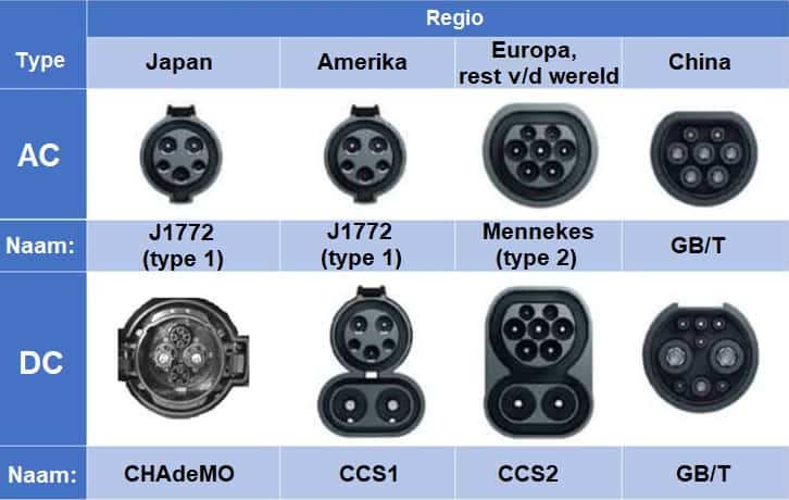
In the image below, you can see the plugs used in other parts of the world. A distinction is made between AC and DC, where the DC variant often extends the AC connector.


Electronic Vehicle Supply Equipment (EVSE):
Public charging facilities are always equipped with an interface with EVSE (Electronic Vehicle Supply Equipment). This ensures security and communication. The EVSE performs the following functions, among others:
- Checking connections: after confirming that all plugs are connected and locked, the charging mode starts;
- Self-diagnosis: if errors are detected, the power supply is interrupted;
- Leakage current detection: any form of leakage current interrupts the power supply;
- Current regulation: communicates with the onboard charger in the car via a PWM signal to limit current intensity.
Charging Options:
When charging with alternating current (AC), electricity from the power grid is converted into direct current (DC) in the car. The disadvantage of AC charging is that there is a considerable chance of induction effects and losses due to conductor resistance. Additionally, within the car, the conversion from AC to DC must occur before the energy reaches the battery, thereby limiting the charging current.
Charging with direct current (DC) allows for “super” fast charging. There is no AC/DC conversion in the onboard charger, but outside the vehicle, allowing the battery to be charged with higher power and fill up faster. This is ideal for a quick charge during a coffee break along the highway for continued travel.
The ways and speeds by which a vehicle can be charged can be divided into four different modes. Mode 1, 2, 3, and 4 indicate how the vehicle is connected to the charging source.
- Mode 1: charging occurs directly through the household power supply. In the vehicle, the voltage is converted from AC (alternating current) to DC (direct current). The charging system offers protection as there is no current limitation or feedback from the vehicle to the socket. This charging method is rarely used due to the risks of danger and defects and is therefore banned in many countries.
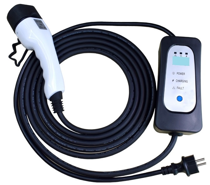
- Mode 2: like in mode 1, the wall socket of a home connection is used and limits the charging current to 16 A with a power of 3.68 kW. However, to prevent overloading, the power is generally limited by the charging cables to 2.3 kW (approximately 10 A). With mode 2, the charging station is a mobile charger that can be taken along. In the vehicle, the onboard charger converts AC into DC.

- Mode 3: charging uses a fixed charging station or wallbox connected to a building’s power network, just like in mode 2. The mode 3 charger is suitable for AC charging and powers from 3.68 to 22 kW. Again, the AC is converted to DC in the vehicle’s power electronics.
- Mode 4: whereas modes 1 to 3 use alternating current that must be converted to direct current in the vehicle, in mode 4 charging, the conversion from alternating current to direct current takes place in the charging station itself. The direct current is delivered directly to the battery pack, known as DC charging or fast charging. A DC charging station for mode 4 charging requires an input voltage of at least 480 volts and delivers power starting from 43 kW.
Charging Times:
The charging times of hybrid and electric vehicles can be determined by dividing the battery capacity by the delivered power of the charger.
The available charging power is not only determined by the type of charger and charging cable but also by the maximum charging power for which the vehicle’s power electronics are suitable. New luxury cars are equipped with increasingly larger batteries with more capacity for longer ranges, but as the charging power increases, the charging time can even decrease. For example, we compare a VW e-Golf (32 kWh) to a Mercedes EQS SUV 500 (108.4 kWh). Not all vehicles can charge to 100% with DC. DC charging stops at 80%. The last 20% are charged at lower power via AC to protect the HV battery.
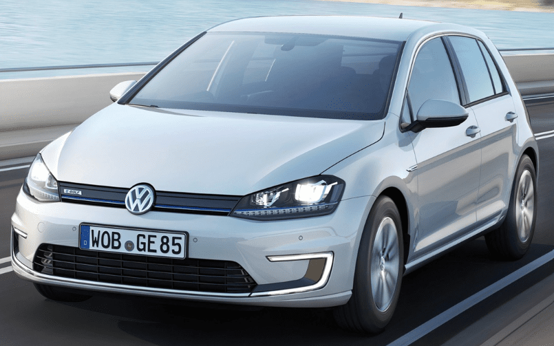
VW e-Golf (32 kWh)
AC charging:
With a Type 2 charging plug, the battery pack can be charged via AC. The maximum charging power of the onboard charger is 3.7 kW. When the battery pack is charged from 20% through a charging station (mode 3), it takes approximately 7 hours. Explanation: 80% (charging) of 32 kWh = 25.6 kWh. We calculate the charging time by dividing the necessary power by the delivered power: (25.6 / 3.68) = 6.96 hours (6 hours and 58 minutes).
When charging via the socket (mode 2), the power is limited to 2.3 kW, resulting in a charging time of 11.13 hours (11 hours and 8 minutes).
DC charging:
When fast charging with direct current at 44 kW, the battery is fully charged after 0.58 hours (35 minutes).

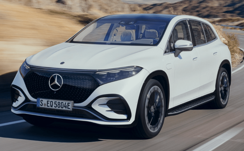
Mercedes EQS SUV 500 4MATIC (108.4 kWh)
AC charging:
With a Type 2 charging plug, the battery pack can be charged via AC. The maximum charging power of the onboard charger is 11 kW.Assuming we start charging from 20%, the delivered power of the charging facility amounts to 86.72 kW.Charging via the charging station takes approximately 7.88 hours (7 hours and 53 minutes).
DC charging:
With mode 4, it is possible to charge up to 207 kW. The charging time is: (86.72 / 207) = 0.42 hours (25 minutes).
Charging Costs:
There are many providers of charging cards. Various websites offer overviews with rates. In this section, we base our calculations on the energy rates that were valid in March 2023, disregarding subscription fees or session start fees but focusing solely on energy prices.
- Netherlands AC €0.60/kWh
- Netherlands DC €0.85/kWh
- Belgium and Luxembourg €0.65/kWh
- Europe: AC €0.51/kWh
- Europe: DC €0.87/kWh
In the examples of the VW e-Golf and the Mercedes EQS, we calculate the charging costs based on the charging power and the fact that charging begins from 20% range.
- VW e-Golf: based on the charging power of 25.6 kW, it costs €15.36 in the Netherlands for AC charging and €21.76 for DC charging. Total range: 190 km.
- Mercedes EQS: with a charging power of 86.72 kW, it costs €52 in the Netherlands for AC charging and €73.70 for DC charging. The range is around 485 km.
Communication Between Charging Station and Vehicle:
The charging interface module enables communication between the charging station and the vehicle. Through the so-called “Proximity Pilot” and the “Control Pilot”, abbreviated as “PP” and “CP”, it is indicated that a charging plug is connected, and the allowable charging current is determined. The functioning of the PP and the CP is explained in the following two sections.
In the image, we see the CP and PP in the American Type 1 (left) and European Type 2 Mennekes plug (right), both combined with the DC charging plug. Our focus is on the right plug with the CP, PP, the three phases (L1 to L3) with neutral wire (N), and the so-called Protective Earth (PE).

This section uses the following diagram, which is based on the European standard (IEC 62196-2). This is the Type 2 connector, also known as the Mennekes connector. In the diagram, we see (from left to right) the following components:
- EVSE controller: this is the module built into the charging station or wallbox;
- Charging plug: besides the charging current, the PP and CP communicate between the EVSE controller and the vehicle controller;
- Vehicle controller: the electronics in the vehicle engage the charging process once several conditions are met.
Proximity Pilot:
The proximity pilot has two functions: registering whether a charging cable is connected and identifying what type of charging cable is connected so that the maximum charging current can be determined.
In the diagram below, the PP circuit is marked in red. It shows a voltage divider between R1 and R2, powered by 5 volts. The control unit measures the voltage between R1 and R2 (indicated by a voltmeter for clarity). Resistor R1 acts as a pull-up resistor.
- If no charging plug is connected, there is no voltage divider. Resistor R1 does not take up any voltage, resulting in a measured voltage of 5 volts;
- When the charging plug is connected, a series connection is formed. With the given resistor values, the control unit will measure a voltage of 3.1 volts.
The resistance value in the charging plug indicates the maximum current that may pass through the charging cable. These resistance values are as follows:
- 100 ohms: maximum 63 A;
- 220 ohms: maximum 32A;
- 680 ohms: maximum 20 A;
- 1500 ohms: maximum 13A.
The resistance value in the example is 220 ohms, indicating the strength of the current through this charging cable may not exceed 32 A. A higher or lower resistance causes a different voltage division, thus resulting in a different input voltage for the controller.
The North American connectors adhere to the standard: SAE J1772. This Type 1 charging plug differs from the European version:
- Single phase AC instead of three-phase AC in the European Type 2 plug;
- Manual locking hook. The extra voltage divider enables an additional safety feature. When it is recognized that the button is pressed, the charging system immediately shuts down.
The diagram below shows the American version.
Specifically, the manual locking hook provides an extension to the Proximity Pilot circuit.
- There is a voltage divider in the connector;
- Switch S3 is parallel to resistor R7. At rest, the switch is closed, bypassing resistor R7;
- When removing the plug, the driver must operate the locking hook to pull the plug out of the vehicle. During the press of this hook, S3 opens. Resistor R7 becomes part of the voltage divider.
Control Pilot:
The CP monitors the charging process from the request to start charging until the termination of charging when the battery is fully charged. The CP enables communication between the EVSE controller in the charging equipment and the vehicle.
- After connecting the charging cable to the charging station, the EVSE controller applies a voltage of 12 volts to the Control Pilot connection of the charging plug.
- Once the charging plug is connected to the vehicle, the voltage drops to approximately 9 volts due to the voltage divider between R3 and R4;
- via the ST2 (Schmitt trigger), the controller measures the incoming voltage.
The current flow with an attached charging cable is marked in red.
- After registering the 9 volts, the EVSE controller energizes relay K2. Instead of the 12-volt power supply, the oscillator is incorporated into the circuit;
- the oscillator produces a block voltage from -12 to +12 volts;
- the diode ensures that the voltage on the CP connection oscillates between +9 and -12 volts;
- the duty cycle in the PWM signal communicates the maximum allowable charging current to the vehicle, which the EVSE controller provides.
After establishing the PWM signal, the vehicle controller engages relay K1 once the vehicle is ready to begin charging.
- Relay K1 connects resistor R5 to ground;
- in the parallel connection between R4 and R5, the positive pulse of the PWM signal drops to 6 volts;
- The EVSE controller in the charging equipment measures the 6-volt signal and now connects the power supply to the charging cable to charge the battery.
The image below shows the Control Pilot signal, depicting the voltage trend over time. This voltage trend can be measured at the Control Pilot connection of the charging plug while connected.
- Status A: there is no connection with the vehicle. As long as no charging cable is connected, the voltage remains at 12 volts;
- Status B: Electric Vehicle is connected. Relay K2 is energized. The voltage drops to 9 volts because of the diode in the circuit;
- Status C: Relay K1 is energized. This is “the trigger” for the charging unit to start the charging process.

Status D and E indicate when an action is needed for ventilation or to terminate the charging process due to a detected fault.
Electrical Network:
In the section “Charging Options,” modes 1 through 4 were discussed. One can choose to charge the vehicle at home using a home charger, wallbox, charging station, or fast charger along the highway. Especially charging at home with personal facilities is growing in popularity. A home charger can simply be connected to an outlet, but to achieve a shorter charging time with more current, a personal wallbox can be connected by modifying the home’s electrical panel. We first look at the concepts of single-phase and three-phase alternating current.
In a single-phase connection, a “standard” electrical cable with three wires is visible:
- brown: live wire;
- blue: neutral wire;
- yellow/green: earth wire.
In a single-phase charging station or wallbox, electricity flows through two wires (the live wire and the neutral wire).

A single-phase wallbox or charging station uses the standard 230 V connection of home electronics. The maximum power is 16 A, with the maximum charging power of a single-phase charger being 3.7 kW. A 60 kW battery pack charges with this power in approximately 16 hours, which is relatively long. Most new electric cars have higher capacities.
It is possible to increase the maximum current strength in the home’s electrical panel to provide more capacity for a 32 A single-phase charger. In that case, one can charge with up to 7.4 kW. However, with a single-phase charger, the risk of overloading the electrical panel exists, leading to a power outage. Besides a charging station, numerous other electrical devices use the power grid, including the washing machine, dishwasher, hob, and heat pump. Load balancing can maximize capacity utilization:
- During the day, multiple electrical devices are likely in use, reducing the charging current for the vehicle;
- At night, most devices are off, allowing the vehicle more charging capacity.
For faster charging, it is possible to connect the charging station or wallbox to the electrical panel via a three-phase connection. This does not necessarily require heavy current. In a three-phase connection, two additional wires are visible:
- black: additional live wire;
- gray: additional live wire.
In a three-phase charging station, electricity flows through four wires (the three live wires and the neutral wire).
The charging power of a charging station or wallbox on a three-phase connection is higher than in a single-phase setting, allowing the vehicle to charge faster. The maximum vehicle charging current is never exceeded. Some vehicles are only suitable for charging up to 3.7 kW. Creating a three-phase connection is pointless in such cases. Vehicles can also be suitable for 7.4 or 11 kW: in these cases, increasing capacity (3 * 16 A) from the electrical panel is worthwhile.

In older houses, a single-phase connection (up to 35 A) is often found in the electrical panel. All three phases are present, but only one is connected.
The electrical panel can be modified so that all three phases are used. Newer houses, where the panel is prepared for more electrical consumers (such as solar panels, an induction hob, and a heat pump), might have a three-phase connection installed from the start. In that case, it says “3×220/230V or 3×380/400 volts” on the electricity meter. A total of four wires – the three live wires and the neutral wire – emerge from the panel’s bottom. Depending on the panel, the group is secured to 1x25A, 1x30A, or 1.35A. The greater the stated current strength, the more current can be used simultaneously.
The image below shows five situations from a single-phase to a three-phase connection in the electrical panel, including the use of a single-phase or three-phase charger.

Single Phase: With the emergency charger, one can charge the vehicle via the socket. A wallbox allows charging up to 16A with a single-phase group without load balancing, and up to 32A with load balancing. The 32A can only be achieved when no other consumers in the house are active.
For outputs up to 7.4 kW, a single-phase network with load balancing is possible. When using multiple high-consumption electrical devices in the home, such as the washing machine/dryer, dishwasher, and heat pump, the power will decrease to prevent overload. In practice, the power can decrease by up to 50%. Transitioning from single-phase to three-phase is therefore advisable.
Three Phase: When excessive current is demanded at the same time, it can cause overload and activate the protection, resulting in a power outage. It’s therefore essential that the network can deliver enough electricity. With a three-phase connection, more current can be simultaneously provided. Three-phase groups are typically secured up to 25A.
- 11 kW: strengthening of the meter cabinet is necessary. Transitioning from single-phase to three-phase is sufficient;
- 22 kW: apart from transitioning from single-phase to three-phase, strengthening to 35A is necessary.
Modifying to 22 kW and 35A is hardly interesting for individuals. Due to the strengthening, one will have to pay an extra annual fixed fee of approximately €1000,-. For each additional heavy step (3x63A or 3x80A), extra payment is necessary. Additionally, not many electric vehicles are currently suitable for charging with such high alternating currents:

The expectation is that the number of vehicles capable of charging up to 22 kW on AC will increase in the coming years.