Introduction:
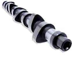
The camshaft is an essential part of the engine. The camshaft ensures that the valves are opened and closed, allowing air to flow in and out of the cylinder. The camshaft rotates, causing the cam to push the valve open against the spring tension of the valve spring. The valve spring ensures that the open valve closes when the cam rotates further.
The camshaft is located above or below in the cylinder head, or at the bottom of the engine block. It is driven by the timing belt, chain, or gears. See more about this in the chapter distribution.
Overhead Camshaft:
Nowadays, only overhead camshafts are used. The camshaft is placed in the cylinder head. The advantage of engines with an overhead camshaft is that they can handle higher RPMs than engines with an underslung camshaft.
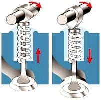
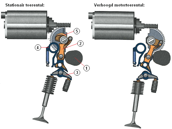
In the left image, the valve is closed because the valve spring pushes the valve shut, and the camshaft rotates clockwise. In the right image, the camshaft is rotated, causing the cam to push the valve down. The spring is now compressed, pushing the valve down. As the camshaft rotates further, the valve spring will push the valve back up. The valve spring exerts a counterpressure of about 20 kg.
The valves of a four-stroke engine are opened by 1 or 2 camshafts. In the version with 1 camshaft, it operates both the intake and exhaust valves.
In the version with 2 camshafts, one camshaft operates the intake valve(s), and the other the exhaust valve(s). The 2 camshafts can be driven by one timing belt in series, but there are also systems where one camshaft drives the other via a separate belt or chain (see the images below).
The images below are merely examples of the construction with the timing belt. The principle is the same with a timing chain.
The top left image shows an engine with a single camshaft. This operates both the intake and exhaust valves. This is usually applied in, for example, four-cylinder engines with 8 or 12 valves (thus with 2 or 3 valves per cylinder).
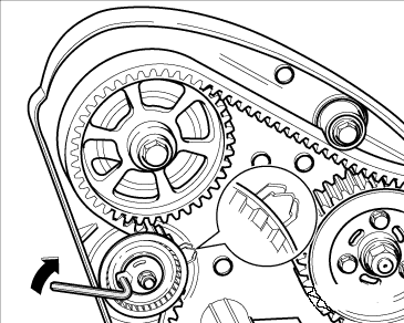
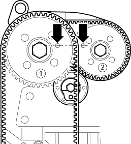
The middle image shows an engine with a double camshaft, driven by two timing belts. The camshaft gear (1) is directly driven by the crankshaft with the large belt. At the back of the pulley of gear 1 is a smaller gear, over which the rear belt runs. This rear (small) belt drives the camshaft gear (2). The small belt requires a separate tensioner. It is usually applied in four-cylinder engines with 16 or more valves (thus 4 or more valves per cylinder).
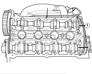
The right image shows an engine with two camshafts. The camshafts are driven by both a belt and a chain. Camshaft 1 is driven by the timing belt, which is driven by the crankshaft. Camshaft 2 is driven by the chain, which is driven by camshaft 1. This chain is mounted under the valve cover with a tensioner or adjustment mechanism. This is usually applied in, for example, four-cylinder engines with 16 or more valves (four or more valves per cylinder).
Underslung Camshaft:
In the past, engines were built with an underslung camshaft. Nowadays, only overhead camshafts are used in passenger car engines. The construction with an underslung camshaft is fading away. The disadvantage of this construction is that these engines handle lower RPMs due to a lot of mass between the camshaft and the valve. At high RPMs, excessive clearance occurs, and the valve won’t open and close at the right times.
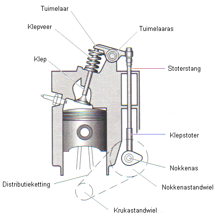
The crankshaft drives the underslung camshaft via a short timing chain or belt (see the image below). The camshaft pushes the tappet and pushrod straight up. The right side of the rocker arm is lifted. The rocker arm ‘rocks’ over the rocker arm shaft, pushing the left side down. Consequently, the valve is pushed down against the force of the valve spring. When the camshaft rotates further, the valve spring closes the valve, and the rocker arm returns to its starting position.
High-performance Camshafts:
When the cam is more oval and longer, the valve will remain open longer. This allows more air to flow into the cylinder, resulting in increased power output.
This principle is used, among others, in engine tuning. It is called ‘high-performance camshafts’. When the tip is sharper (more pointed), the valve will close faster. It also needs to be slightly convex, otherwise, the valve will slam back into the seat at high speed, causing excessive wear on the valve seats. In engine design, this is also meticulously tested, to ensure camshafts are placed that are optimal for power, fuel consumption, and emissions.
Valve Overlap:
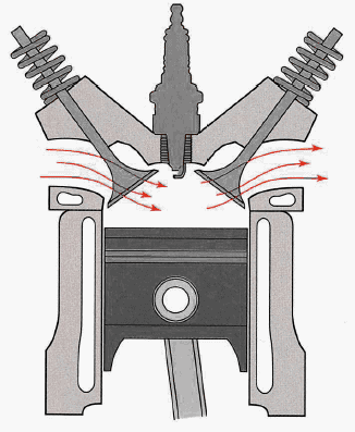
During valve overlap, both the intake and exhaust valves are open simultaneously for a brief moment. At the end of the exhaust stroke, when the piston is near the TDC, the intake valve opens before the exhaust valve closes. In this situation, the speed of the exhaust gases leaving the combustion chamber is so high that intake air is drawn in through vacuum action. After the exhaust valve closes and the piston moves to BDC, the intake valve fully opens. This fills the combustion chamber with intake air.
The advantage of valve overlap is that the speed of the incoming air is increased when the intake valve opens, resulting in a higher volumetric efficiency.
The image shows the situation where the intake valve (left) and the exhaust valve (right) are open simultaneously.
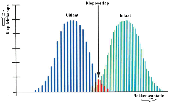
The diagram shows the opening and closing of the exhaust and intake valves. As the camshaft rotates, the exhaust valve opens and closes (the blue lines). In the middle of the graph, valve overlap occurs. This is represented in red. The intake valve (represented by the green lines) is already partially open here.
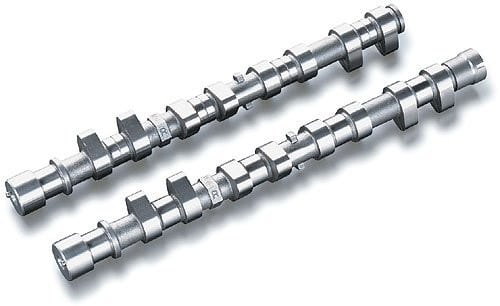
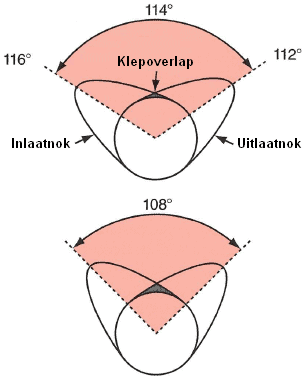
Valve overlap is achieved by the cam shape. The image below shows that in the upper camshaft, the highest cams are 114 degrees apart. In the middle of the image, valve overlap occurs because the end of the intake cam and the beginning of the exhaust cam are higher than the round part of the camshaft. This is the part where the intake and exhaust valves are open simultaneously.
The closer the cams are placed together, the more overlap there is. This can be seen in the difference between the upper and lower camshaft, where the cams in the lower camshaft are 108 degrees apart.
Valve overlap always occurs and cannot be changed due to the fixed cam shape on the camshaft. The amount of valve overlap is determined by the engine designer.
Variable Valve Timing and Lift:
The engine’s power largely depends on the camshaft. If the cam has long and oval shapes, the valves stay open longer. This allows for more air in and out of the engine, resulting in more power. If the cams are shorter and more pointed, the valve will open less and close sooner, allowing less air in and out, thus generating less power. The benefit is that this can reduce fuel consumption.
Low RPMs with low load require:
- Intake valves to open late and close early.
- Exhaust valves to open late and close early.
High RPMs with high load demand:
- Intake valves to open early and close late.
- Exhaust valves to open early and close late.
Car manufacturers always look for a middle ground. Variable valve timing adjusts the camshaft to the required position for the engine’s RPM. Variable valve lift is also a technique to achieve various benefits by changing the distance the valve opens.
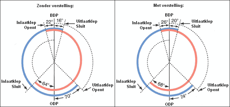
In variable valve timing, the camshaft rotates relative to the adjustable camshaft gear (see image). This system allows for the control of when the valves open earlier or later, but not for valves to stay open longer. If the valve opens earlier, it will also close earlier since the camshaft shape remains the same. More explanation on variable valve timing is provided on the page.
Variable valve lift is a technique allowing for adjustable valve lift. This regulates how far the valve opens, benefiting both fuel consumption and engine power. The image below is an example. This is BMW’s Valvetronic.
Variable valve lift is only applied to the intake camshaft. Several techniques by different manufacturers are used. Various techniques are described in more detail on the variable valve lift page.
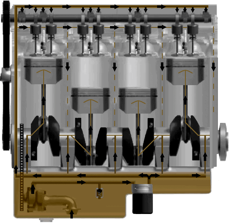
Lubrication:
The camshaft must be lubricated, as with all other moving components in the engine. Through pipes with holes or nozzles, the camshaft is supplied with oil in the right places. The operation of the entire lubrication system is described on the lubrication system page.