Introduction:
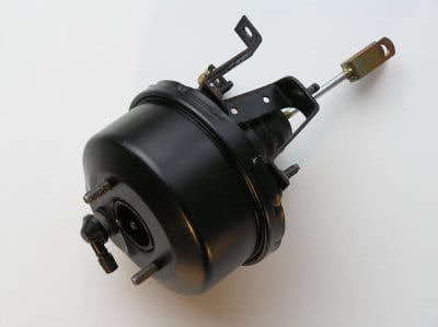
Vacuum brake boosters are used on nearly all passenger cars. With the help of the brake booster, the driver needs to apply less force to the brake pedal to achieve the same braking effect as in a car without a brake booster. A brake booster helps move the pistons in the master cylinder. The brake booster is located in the engine compartment, connected to the brake pedal by a rod (see the right rod in the image). The master cylinder is mounted directly on the brake booster (left side of the image). The pressure applied to the brake pedal is increased approximately 3 to 4 times.
Operation of the vacuum brake booster:
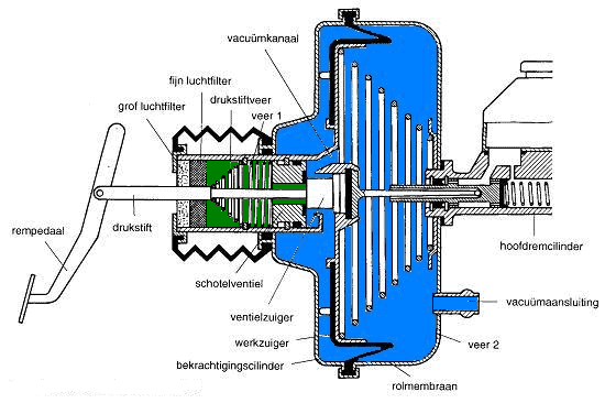
Idle state:
The engine is running, but the brakes are not being applied. A vacuum exists in both the left and right sides of the booster cylinder. The vacuum occupies the blue-colored areas. Air is drawn from the booster through the vacuum connection. This is achieved by a connection to the intake manifold or via a separate vacuum pump. The atmospheric pressure (green) is isolated from the booster. The spring pushes the working piston as far left as possible.
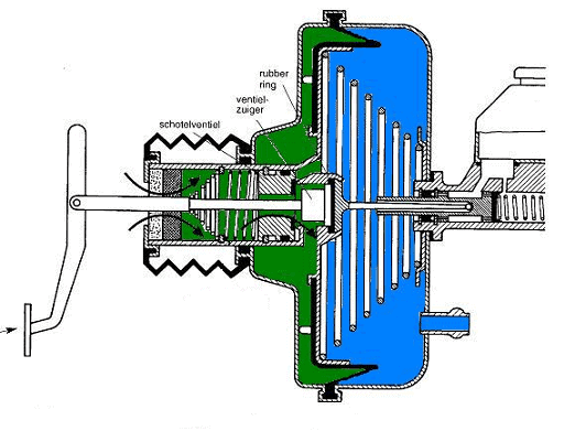
Starting to brake:
When the brake pedal is operated, the valve piston moves to the right. It separates from the diaphragm valve, allowing the left side of the booster cylinder to partially fill with atmospheric pressure (green). The vacuum (blue) disappears. To the left of the working piston, there is now pressure lower than atmospheric pressure but higher than the vacuum. The boost is not yet at its maximum at this stage.
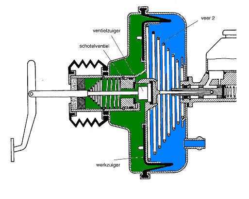
Maximum boost:
The brake pedal is pushed further. The connection between the valve piston and the diaphragm valve remains open, allowing the left side to fill with even more atmospheric pressure. Maximum atmospheric pressure now exists on the left side of the booster, and maximum vacuum on the right. When the brake pedal is fully pressed, the spring in the brake booster is also compressed. This provides maximum braking force.
When the brake pedal is released, the spring in the brake booster pushes the working piston back to the left. The valve piston will rest against the diaphragm valve again, opening the vacuum port. The atmospheric pressure disappears from the left side of the booster cylinder, and a vacuum is re-established. The brake booster is now back in the idle state. The situation depicted in image 1 is now applicable again.
Vacuum connection and pump of the vacuum brake booster:
The required vacuum for a vacuum brake booster is often obtained from the engine vacuum in a gasoline engine. A hose runs from the brake booster to the intake manifold. Due to the vacuum present in the intake manifold, vacuum is also drawn from the booster. If the engine is turned off and the brake pedal is pumped a few times, the pedal will feel hard. This is because all the vacuum has disappeared from the brake booster. When the engine is restarted, the pedal will depress again and can be pressed further. This must always be considered when towing a vehicle; in the car where the engine is not running, 3 to 4 times as much force will need to be applied to the pedal. Additionally, the power steering will not work. Therefore, it is advisable to drive carefully.
It can occur that the pedal feels hard immediately after the engine is turned off; it seems as if the vacuum disappears immediately. This can be caused by a torn vacuum hose between the brake booster and the engine, or by a defective check valve in the hose. This is usually a round piece of plastic between two parts of the hose.
If the specific hose is torn, it should be replaced as soon as possible. If it tears further or breaks, the entire brake booster function will be lost.
There are two different types of vacuum pumps, namely the vane pump and the diaphragm pump. The vane pump is also known as the tandem pump or the vacuum pump. The operation and application of these pumps are described on the vacuum pump page.
Hydraulic brake booster:
Hydraulic brake boosters are rarely used in passenger cars. Therefore, this page does not go into great detail. In hydraulic brake boosters, the force exerted on the master cylinder is supported by fluid pressure. The hydraulic brake booster is placed between the brake pedal and the master cylinder.
In some systems, the brake boosting system (via the accumulator) is combined with power steering. In the image below, you can see by the colors which lines belong to which components. All visible lines use hydraulic oil or ATF (Automatic Transmission Fluid). In the system with the master cylinder and brake lines to the brake calipers/drums, regular brake fluid is used. The fluid from the brake booster and master cylinder is therefore different and must not be mixed.
Components of the hydraulic brake boosting system:
- Hydraulic brake booster: The supplied oil will support the pedal force in this brake booster.
- Master cylinder: This is where the pressure build-up of the brake fluid begins.
- Pump: The pump (driven by belt or electric motor) provides the necessary pressure. In such systems, the same pump is often used for multiple systems, such as power steering, height adjustment, hydropneumatic suspension, etc. Other systems use a separate pump.
- Reservoir: The reservoir stores hydraulic oil or ATF.
- Accumulator: The oil is stored under high pressure, between 36 and 57 bar, in the accumulator.
- Flow controller: This ensures that the accumulator remains filled and regulates the flow of fluid from the brake booster and power steering.