Introduction to Auxiliary Heaters:
Passenger cars and commercial vehicles can be equipped with an auxiliary heater or electric auxiliary heater. Especially in countries with long periods of low temperatures, such as Scandinavia, auxiliary heating is very common. In the Netherlands, the auxiliary heater is mainly seen in exclusive passenger vehicles.
The auxiliary heater is connected to the fuel system and can operate with the engine off. It is often activated before a cold start of the engine. The benefits of using the auxiliary heater include:
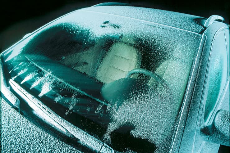
- The interior is at a higher temperature when entering. Not only does this provide more comfort, but it also melts any ice formation on the windows;
- The engine’s cooling system is preheated, which allows for a better cold start. The engine reaches its operating temperature earlier. This not only benefits the lifespan (reduced wear) but also results in fewer harmful emissions compared to a vehicle without this preheating.
An auxiliary heater can automatically activate during a cold start in low outside temperatures. With a cold start, it can warm a diesel engine in just 5 minutes. The auxiliary heater shuts off automatically upon reaching the operating temperature.
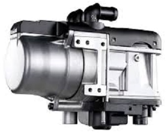
The auxiliary heater is connected to both the fuel and cooling systems. Fuel ignites in the auxiliary heater and heats the coolant in the adjacent coolant channel.
We can encounter the auxiliary heater in various locations in and around the car:
- In the engine compartment: the auxiliary heater can be placed behind the front bumper or in a wheel well;
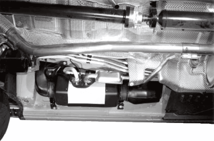
- Under the car: the auxiliary heater is often mounted beneath the vehicle. The underbody covering protects it from dirt.
The following image shows the installation location in a Volkswagen Transporter (T5).
Operation of the Auxiliary Heater:
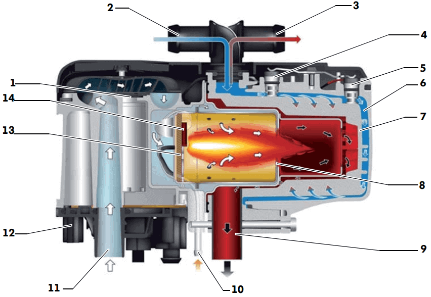
The fuel pump supplies fuel to the auxiliary heater. Through the fuel supply (number 10 in the image below), the fuel enters a so-called combustion chamber. In this chamber, the fan (1) blows air from the intake channel (11) through a metal screen to the combustion chamber where it mixes with the incoming fuel. As the glow plug (14) heats, the fuel evaporates in this metal screen. The fuel ignites in the combustion chamber. When the phototransistor in the flame monitor detects a stable flame in the glow tube, it reports this to the control unit (12), which immediately turns off the glow plug to prevent overheating. The combustion exhaust gases exit the auxiliary heater via the exhaust (10). The exhaust pipe’s end could be located in the engine compartment or under the passenger area.
Legend:
- fan;
- coolant inlet;
- coolant outlet;
- temperature sensor;
- overheat sensor;
- water channel;
- heat exchanger;
- burners with combustion chamber and flame tube;
- combustion exhaust outlet;
- fuel supply;
- combustion air intake;
- control unit;
- metal screen;
- glow plug with flame monitoring.
Image source: Volkswagen AG.
The coolant supplied through the intake channel (2) flows through the water channels (6) along the combustion chamber. This creates a heat exchanger effect. The warmed coolant exits the auxiliary heater via the outlet (3) and flows to the heater core in the heater housing under the dashboard.
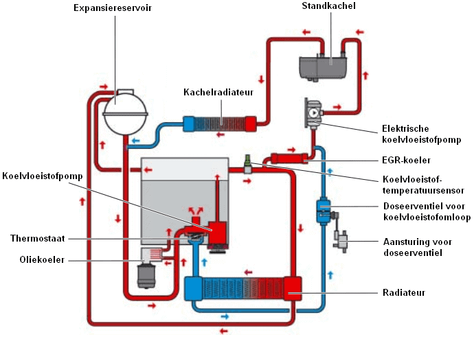
Cooling System for Auxiliary Heaters:
The existing vehicle cooling system has been expanded with additional lines and components for the auxiliary heater. This includes an electric coolant pump that transports coolant to the auxiliary heater when the engine is off. Additionally, the coolant line from the auxiliary heater runs directly to the heater core: this warms up first. The blower or interior fan will activate to blow (cold) interior air through the warmed heater core into the cabin.
The coolant line continues after the heater core to the combustion engine. Besides warming up the engine’s cooling system, the oil cooler will also warm up. Once the engine starts, the engine oil in the oil cooler will warm up faster.
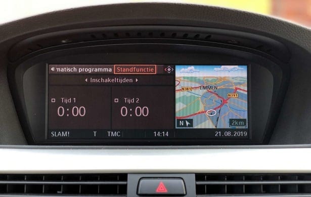
Activating the Auxiliary Heater:
The auxiliary heater can typically be manually activated with a remote control. Modern systems also allow programming the activation of the auxiliary heater. Through the onboard computer, users can set the activation times so that the car is warm the next morning before departure.

Electric Auxiliary Heating:
Sometimes, the combustion engine is insufficient to retain enough heat from the cooling system during cold outside temperatures. With low engine load, the coolant temperature drops, causing the heater core, and the air flowing through it, to remain too cold. An electric auxiliary heater solves this issue.
As an example, consider the electric auxiliary heating in a Smart ForTwo 450.
The electric auxiliary heating is activated when the following conditions are met:
- Outside temperature below 8 degrees Celsius;
- Coolant temperature lower than 85 degrees Celsius;
- Temperature selection lever in the maximum warm position;
- Blower activated;
- Combustion engine on.
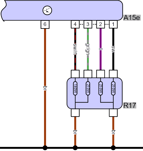
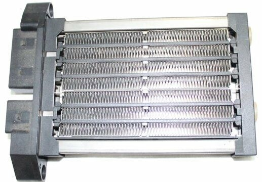
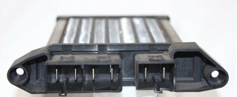
The auxiliary heating consists of four heating elements in a housing (R17) controlled by a control unit (A15e). Once current flows through a resistor, it heats up. The resistors are located in an air duct of the heater housing: the glowing resistor heats the passing air. The current through the resistors increases to 25 to 50 Amperes, depending on the temperature. The initial current is high, but the current decreases once the resistors are heated. It takes less energy to maintain the resistors’ heat than to initially heat them.
The maximum power is approximately 900 Watts at 14 volts.
The following two images show the electric heating element.
Related page: