Topics:
- Introduction
- Controlled and Uncontrolled Autogas Systems
- Autogas and Gas Tank
- Filling Connection
- Gas Shut-off Valve
- Gasoline Shut-off Valve
- Switching from Gasoline to Gas
- Operation of the Vaporizer
- System with Stepper Motor with Vapor Hose (AMS)
- Vapor Gas Injection (VSI/EGI)
- Operation of the EGI Vaporizer
- Liquid Gas Injection (LPi)
- Coupling Block (LPi)
- Injectors (LPi)
Introduction:
Autogas is used worldwide on a small scale as fuel for passenger car engines. As of 2013, approximately 700,000 vehicles run on this fuel. This number may decrease because the road tax benefit for cars older than 40 years has been removed. The tax rate for these older cars is the same as for a younger car. If the autogas system is removed (and naturally retested), then one can, if the vehicle is between 26 and 40 years old, again benefit from the tax advantage.
Autogas is more environmentally friendly than gasoline or diesel fuels. The exhaust gases are cleaner. Also, the fuel itself is cheaper per liter than gasoline. Consumption with autogas is often slightly higher, but the break-even point is low. The engine power decreases slightly with autogas compared to gasoline, except for the LPi system. More explanation about this is provided at the bottom of this page.
There are 3 different types of autogas systems. These systems are thoroughly explained on this page:
- System with a stepper motor in the vapor hose (AMS) (Single-point injection before the throttle valve)
- Vapor Gas Injection (VSI/EGI) (Multipoint injection at the intake valve)
- Liquid Gas Injection (LPi) (Multipoint injection at the intake valve)
The terms G2 or G3 are often used:
G2 installations use a gas venturi system or a vapor gas injection. A catalytic converter with an oxygen sensor can be present on the car and be similar in equipment to a G3 installation. Despite this, they may not fall under the fiscal benefit of a G3 installation, either because the vehicle does not meet the ECE94-12 emission standards, or because the vehicle has not been tested at a recognized inspection authority. G3 installations use the control times of the gasoline injectors calculated by the engine management system. These times are converted into control times for the gas injectors.
Controlled and Uncontrolled Autogas Systems:
For older cars (oldtimers) without an engine management system, thus without a catalyst and lambda control, an uncontrolled autogas system is used. This conventional system was applied until 1990 when environmental requirements became stricter. There were also more issues with backfires (kickbacks) with the uncontrolled system. A controlled system, as it is still used today, is equipped with an electronic control unit. Using the oxygen sensor, a more precise amount of gas can be injected. The catalyst converts harmful exhaust gases into less harmful ones.
Autogas and Gas Tank:
The composition of autogas varies in summer between 30% propane and 70% butane, and in winter up to 70% propane and 30% butane. Butane cannot leave the tank at a temperature of -10 degrees because the vapor pressure is too low, so the percentage must be lower in winter than in summer. This is done automatically at gas stations. If the car is driven very little, there is a chance that fuel problems will arise because the composition in the tank was from a warmer period.
The liquid autogas is stored in the tank. The gas is under a working pressure of a maximum of 2500 kPa (25 bar).
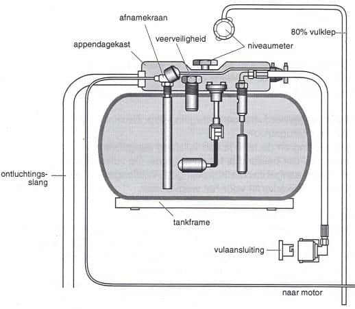
A tank with liquid autogas should never be filled to 100% because there would not be enough space for the gas to expand when heated. The gas tank is designed so that it can only be filled to 80%. The liquid autogas leaves the tank via the electromagnetic take-off valve, which opens when the engine is started. The liquid autogas then flows through the line to the gas shut-off valve. More about this later on this page.
The date of manufacture is stamped on the tank after fabrication. The tank is found to be in order for the next 10 years. Gas tanks are tested for leaks at a pressure of 3000 kPa (30 bar). The burst pressure of a gas tank is 10,000 kPa (100 bar). A gas-tight box, called the appendage box, is installed around the fittings. The appendage box is connected to the outside air with a vent hose. The purpose of the appendage box is to vent any leak gases to the outside in case of a leak. These leak gases must never enter the interior.
Gas tanks are attached to a steel subframe with tension straps. This steel subframe is bolted to the car’s body. Plastic strips are placed between the tank and the tension straps for protection. The gas tank must not be connected to the body in any other way!
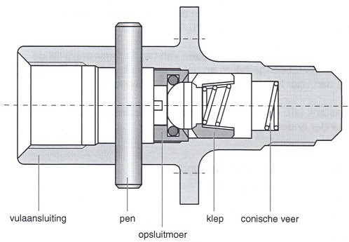
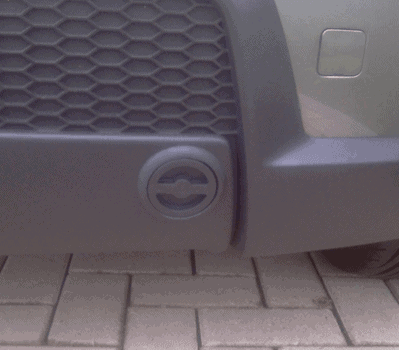
Filling Connection:
The filling connection is threaded. An adapter can be screwed in here. This may be necessary when refueling abroad. The external fill cap is equipped with a check valve that prevents gas from flowing back after filling. The pump at the gas station will press the gas through this filling connection under pressure. Through the filling connection, the gas flows through the fill hose to the gas tank.
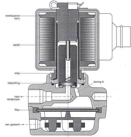
Gas Shut-off Valve:
The gas shut-off valve is mounted as close as possible to the vaporizer. The gas shut-off valve is activated when the ignition is turned on and the fuel selector is set to gas. The control unit controls this gas shut-off valve. The control is stopped when the engine stalls. The autogas that enters the gas shut-off valve from the gas tank flows through the filter. If the coil is not activated, the valve closes the passage to the vaporizer. The autogas then enters bore “A” in the space around and above the valve. Because the autogas presses on the valve, the passage to the vaporizer is tightly closed. Once the coil is activated, the soft iron core becomes magnetic. Due to the magnetism, the valve is pulled upwards. The passage to the vaporizer is now open, allowing autogas to flow to the vaporizer. As soon as the engine is braked, the gas shut-off valve temporarily cuts off the gas supply until the driver gives gas again.
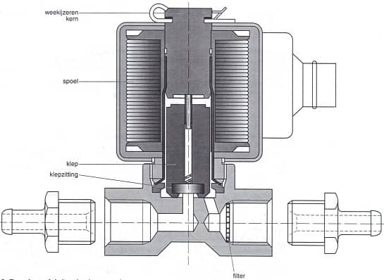
Gasoline Shut-off Valve:
When running on gas, the gasoline supply is shut off. At that moment, the coil is not activated and the valve closes the passage. When switching back from gas to gasoline, the coil is activated and, as a result, the soft iron core becomes magnetic. This causes the valve to be pulled upwards, allowing the gasoline to pass.
Switching from Gasoline to Gas:
When starting on gasoline and switching to gas, this changeover doesn’t happen immediately. The engine temporarily runs on both fuels. This ensures a smooth transition from gasoline to gas. This situation is referred to as the “dual running time.”
The control unit determines how long the engine runs on both fuels simultaneously. For a cold engine, this will be longer than for a warm engine, since vaporization of a fuel is worse in cold outside air. After a few minutes (depending on the system and temperatures), the gasoline supply is completely shut off via the gasoline shut-off valve.
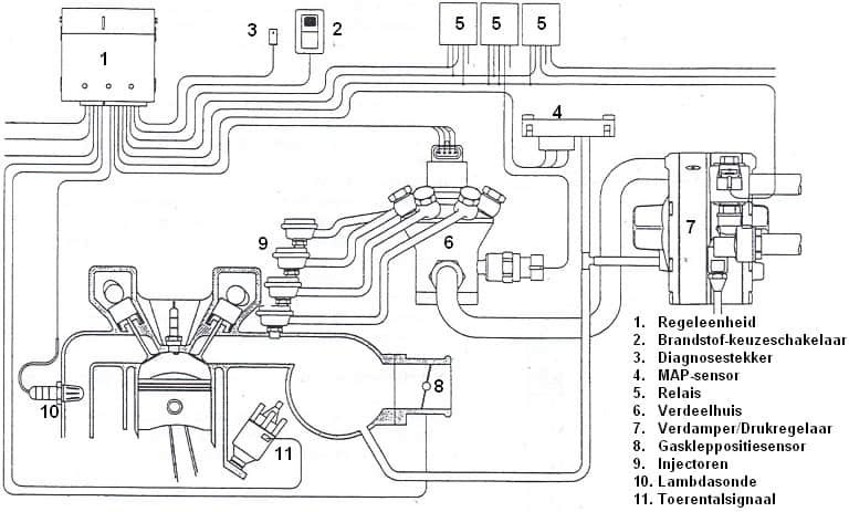
Operation of the Vaporizer:
To make the operation of the vaporizer as clear as possible, the vaporizer in the illustration is drawn as simply as possible. Later on this page, an explanation will be given about a real (EGI) vaporizer, which is considerably more complicated. Therefore, the simple vaporizer is explained first to make the basics clear.
The vaporizer’s task is to make liquid autogas in the tank gaseous. The liquid gas must be evaporated (hence the name vaporizer). Heat is needed to vaporize the liquid gas. This heat is taken from the coolant. The coolant is heated by the engine and is around 90 degrees when the engine is at operating temperature. It is important that the vaporizer heats up as quickly as possible, so the coolant is tapped before the thermostat. This can also be done with the heater circuit, because this supply line is also connected before the thermostat.
Since the vaporizer needs pure heat, it is logical that the engine must be warmed up first before the vaporization process can begin. This is also why you cannot start directly on gas. During a cold start, the engine will run on gasoline for the first few minutes before the system switches to gas.
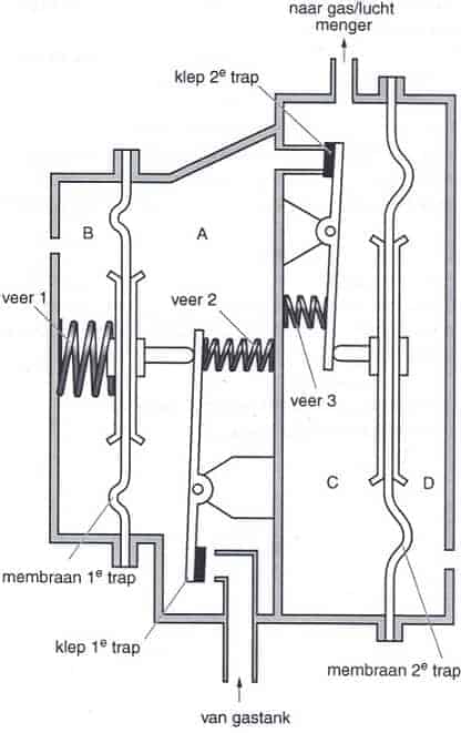
Theoretical Operation of the Vaporizer:
Chamber A is of the first stage, chamber C is the chamber of the second stage.
In chambers B and D, the reference pressure prevails, which in this case is the outside air pressure.
Gas Shut-off Valve Open, Engine Not Running:
The liquid autogas flows from the gas tank along the valve of the 1st stage into chamber A. Here, the autogas transitions from the liquid form to a gaseous state.
The autogas builds up pressure in chamber A. This pressure pushes the membrane of the 1st stage to the left. Spring 1 is compressed, while spring 2 relaxes. When the pressure in chamber A reaches approximately 135kPa, the membrane of the 1st stage moves so far to the left that the valve of the 1st stage closes. No more autogas flows to chamber A. Spring 3 ensures that in this state the valve of the 2nd stage remains closed.
Gas Shut-off Valve Open, Engine Running:
When the engine is running, the intake air causes a vacuum at the outlet of the gas/air mixer. This vacuum propagates through the vapor hose to chamber C (the 2nd stage) of the vaporizer/pressure regulator. The reference pressure in chamber D now ensures that the membrane of the second stage moves to the left. Spring 3 is compressed and the valve of the second stage opens. Autogas now flows from chamber A to chamber C and from there to the engine. Because autogas flows from chamber A to chamber C, the pressure in chamber A drops. The valve of the first stage will open, allowing autogas from the tank to flow again into chamber A. The autogas that flows along the valve of the second stage into chamber C builds up pressure in chamber C. Depending on the engine’s fuel requirement, the membrane of the second stage will take a certain position, so that the passage of the valve of the second stage becomes larger or smaller. The larger the vacuum at the outlets of the gas/air mixer, the more autogas can flow to the engine. There is an equilibrium situation where more or less gas flows along the valves of the first and second stages, depending on the vacuum at the outlets of the gas/air mixer.
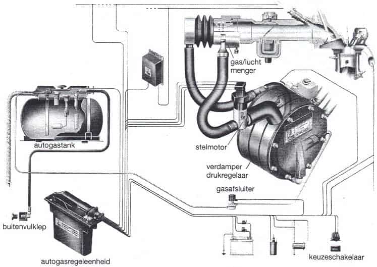
System with Stepper Motor with Vapor Hose (AMS):
This is the AMS system from Vialle. Liquid autogas is in the tank. The vaporizer/pressure regulator ensures the gas evaporates as it exits the tank and that the pressure is reduced. The amount of gas leaving the vaporizer is regulated by the venturi at the gas/air mixer, which creates a vacuum. The greater the vacuum, the more autogas is sucked in. The vacuum depends on the engine speed and load (by the air speed). So, as more revs are made, the amount of gas sucked in is increasingly larger. However, this is not very precise. Fine-tuning is needed to deliver exactly the amount of gas the engine needs. The correct mixture ratio is calculated using the oxygen sensor measurement.
If too little gas is injected, the mixture is lean (lambda > 1). If too much gas, the mixture is too rich (lambda < 1). (The symbol > means greater than and < less than). The oxygen sensor will measure this in the exhaust gases. The engine management will thus recognize the too rich or too lean mixture and adjust the stepper motor. The stepper motor then makes the gas passage larger or smaller. This stepper motor is usually placed on the vaporizer. During a cold start, this stepper motor will be in a neutral position and not yet active. The engine still runs in an “open loop” situation. This means the oxygen sensor signal is not yet used because the cold start enrichment is still active. The disadvantage of the AMS system is that it is single-point injection. The gas is injected before the throttle and is distributed with the air over the different cylinders. Due to the large amount of gas in the intake pipe, the risk of a backfire is high.
Vapor Gas Injection (VSI/EGI):
This is the Vapor Sequential Injection (VSI) or Electronic Vapor Gas Injection (EGI). For convenience, it is now only referred to as EGI. The vapor gas injection system is a multipoint injection system controlled by a control unit. It can now be injected per cylinder instead of centrally before the throttle. This can be with a 4-cylinder engine but also easily with a 6 or 8-cylinder. The gas is injected just before the intake valve. The chance of a backfire is now much smaller compared to the AMS system. With this type of gas installation, it must always start on gasoline. After a short time, the gas system will automatically be engaged.
The autogas comes out of the vaporizer in a gaseous state. The pressure has been lowered in the vaporizer by the pressure regulator. Subsequently, the gas flows to the distribution block. The distribution block doses the amount of gas and distributes it over the injectors using the control grooves. The injectors inject the gaseous gas into the intake manifold, just before the intake valve.
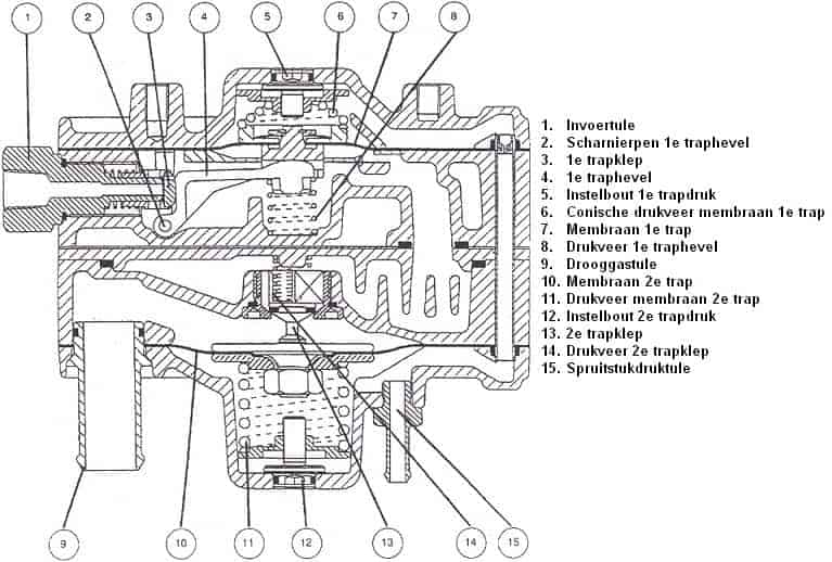
Operation of the EGI Vaporizer:
The following text relates to the illustration below.
- Operation of the First Stage:
In a pressureless state, spring 6 will push against membrane 7, pressing the lever against spring 8 downwards, thereby opening the 1st stage valve 3.
When the gas enters at union 1, the gas will push the membrane 7 up against spring 6. The lever 4 is now free, and spring 8 pushes the lever upwards, thereby closing the 1st stage valve 3.On top of membrane 7 is the engine vacuum, making the 1st stage pressure dependent on the engine vacuum. The pressure in the 1st stage can be adjusted using adjustment screw 5.
1st stage pressure = Set 1st stage pressure – engine vacuum. - Operation of the Second Stage:
The gas in the first stage can initially pass through the open 2nd stage valve 13. The gas then presses against spring 11 and membrane 10, causing the 2nd stage valve 13 to close by spring 14.
At the bottom of membrane 10, the engine vacuum prevails, making the 2nd stage pressure dependent on the engine vacuum. The 2nd stage pressure can be adjusted using adjustment screw 12.
2nd stage pressure = Set 2nd stage pressure – engine vacuum.
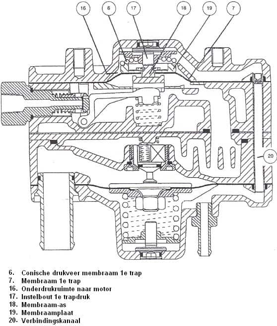
- Overpressure Protection 1st Stage:
When the pressure in the 1st stage becomes too high, membrane 7 together with membrane plate 19 will move upwards.
When the membrane rod 18 rests against adjustment screw 17, the membrane rod 18 can no longer move upwards.
Membrane 7 continues to move upwards with membrane plate 19, causing membrane plate 19 to rest at the narrower part of membrane rod 18. Here, an opening is created through which the gas from the 1st stage can go through chamber 16, channel 20 and manifold pressure fitting 15 to the intake manifold of the engine.
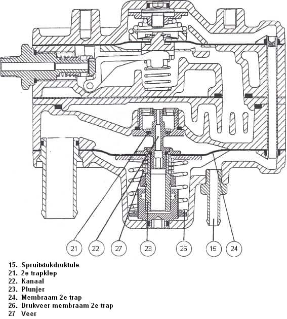
- Feedback:
The gas pressure from the 1st stage can come under plunger 23 via channel 22.
This gas pressure acts on the underside of plunger 23, counteracting the gas pressure from the 1st stage on the 2nd stage valve 21.
Now the gas pressure of the 1st stage on the 2nd stage valve 21 will no longer influence the opening of the 2nd stage valve 21, because the gas pressure of the 1st stage under plunger 23 is directed opposite.
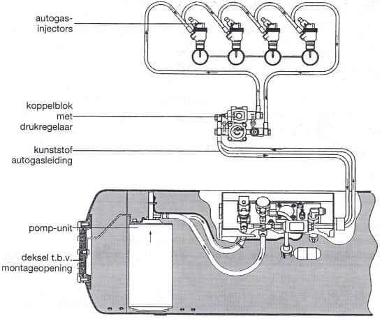
Liquid Gas Injection (LPi)
LPi stands for: Liquid Propane Injection). In liquid gas injection, autogas is injected as a liquid. Therefore, there is no vaporizer in this system.
Because the liquid gas does not have to be vaporized, it can be started on gas without issues. The gasoline injection system is effectively overridden. This does have the drawback that the gasoline injection system can become contaminated due to infrequent use. It is advisable to occasionally drive on gasoline. The LPi system tries to closely mimic the gasoline injection system. The liquid autogas is injected onto the intake valve through the injectors (precisely as with indirectly injected gasoline engines).
The vaporizer and gas/air mixer are replaced by the coupling block and injectors. A pump is installed in the tank to circulate the liquid autogas. The liquid injection is controlled from the existing engine management system that retains and utilizes all its self-learning properties. The LPi system uses only the opening time signal of the gasoline injector and translates it into autogas. Liquid autogas is very precisely dosed, better than gas in vapor form.
The LPi system follows the injection strategy of the gasoline control unit. All options such as fuel cutoff during deceleration, speed limiter, full throttle enrichment, and lambda control are also executed on autogas. With LPi, there is no power loss in the engine. This is due to the absence of the air displacement effect, which remains with vapor dosing. Due to the air displacement effect, the engine’s fill rate decreases by about 6%. Additionally, liquid injection provides a cooling effect for vaporizing the gas in the cylinder, resulting in a better fill rate. This enhances engine performance. However, fuel consumption is still higher than driving with the same engine on gasoline because there is less combustion energy in a kg of gas compared to a kg of gasoline.
A high system pressure is required to inject autogas in liquid form. The system pressure is supplied by the diaphragm pump in the tank. This pumps the autogas via the coupling block to the autogas injectors. The system pressure is regulated by the pressure regulator to 5 bar above the tank pressure.
In case of heating, vapor bubbles could form in the lines. Vapor is compressible and, therefore, not accurately injectable. By circulating the liquid autogas under pressure, heating and possible vapor in the line are prevented. The lines are also made of plastic and insulated against heat.
A filter is also mounted on the return line to catch any impurities and metal particles.
Coupling Block (LPi):
The coupling block forms the connection between the tank and the injectors (see the image below). An electromagnetic valve is included in the coupling block, which opens and closes simultaneously with the take-off valve on the tank. The pressure regulator (which is normally at the vaporizer) and the pressure sensor are also mounted on the coupling block. There are four connections on the coupling block. The flexible high-pressure lines are attached to the coupling block with a banjo bolt. The connections must not be swapped due to the flow of autogas. If a defect occurs, the coupling block must be completely replaced because it absolutely must not be disassembled.
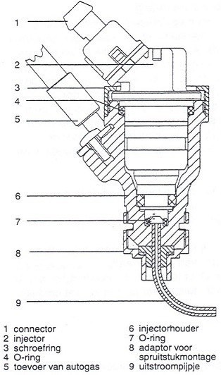
Injectors (LPi):
To inject the liquid autogas, “bottom-feed injectors” are used. This type of injector has the advantage (as opposed to top-feed injectors) that the heat of the injector coil does not cause heating of the autogas. Also, there is almost no autogas left in the injector. The injector coil has a resistance of 1.8 Ohms. A filter is installed for the gas inlet of the bottom-feed injector to prevent coarse assembly dirt from entering the injector.
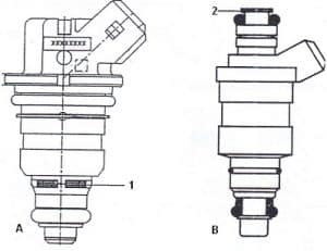
The injectors are placed in a universal injector holder. Seals are provided by O-rings. The injector is held in place by a screwed ring. Depending on the placement on the manifold, the gas is led through the outlet tubes (see component 9 in the image).