Subjects:
- General
- Operation
- Replacing and adjusting unit injectors
- Fuel supply pump
- Custom Distribution
- Fuel cooler
General:
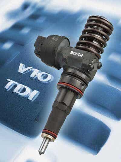
More and more demands are made on modern diesel engines. Consumers are demanding more and more comfort and power, while the government and other authorities are imposing ever stricter environmental requirements. Car manufacturers are forced to come up with cleaner and more fuel-efficient engines that also have to deliver even more power. Examples of this are the common rail and unit injector fuel injection system. The unit injector injection system was developed by Volkswagen.
Volkswagen used unit injector technology for the:
- 1.2 TDIs,
- 1.4 TDIs,
- 1.9SDI,
- 1,9 TDI 105, 110, 115, 130 and 150 hp,
- 2.0 TDIs,
- 2.0SDI,
- 2.5 R5 TDI,
- 5.0 V10 TDI.
Due to the emission requirements, unit injectors are no longer used in new cars, but common rail.
Operation:
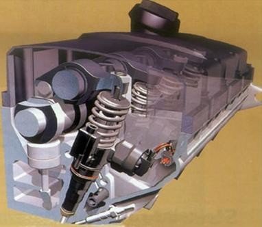
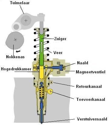
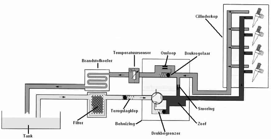
The unit injector injection system is direct fuel injection. An electronic fuel pump pumps the diesel fuel from the tank to the fuel supply of the unit injectors at a pressure of approximately 7,5 bar. The pump element is filled with this pressure. The pump element of the unit injector is actuated by the camshaft via a rocker arm. The pressure build-up in the pump element starts the moment the rocker arm pushes the atomizer needle down. The amount of fuel injected is controlled by the solenoid valve; the longer the control unit activates the solenoid valve, the more is injected.
Multiple injections can be made in succession with the unit injector Worden done:
- Pre-injection: The solenoid valve starts to actuate. By applying pre-injection, the combustion is used more softly, so that the diesel knock is less. The height of the injector needle is 1/3 of the maximum lift height during pre-injection. The opening pressure of the injectors is then 180 bar.
- Main injection: The opening pressure of the main injection injector can be up to approximately 2000 bar. This pressure is reached when the engine gives its maximum power. The main injection ends when the solenoid valve stops driving.
The rocker arms that operate the pistons in the unit injectors are driven by the camshaft. During the pump stroke, a high fuel pressure is built up in the high-pressure chamber. The pressure at the top and bottom of the atomizer needle is the same. As a result, the atomizer needle remains closed.
When the solenoid valve is actuated, the pressure at the bottom of the atomizer needle disappears. The pressure at the top is greater, pushing the plunger needle down.
The fuel supplied to the injector, but not used in the injection, is returned to the tank via the return channel.
Replacing and adjusting unit injectors:
After dismantling or replacing a unit injector, it must be adjusted. This is done on the basis of two measurements.
- The first measurement to be taken is to mount the unit injector straight into the cylinder head. The caliper is used for this.
- The second measurement is to set the maximum stroke that the piston makes in the unit injector.
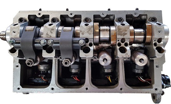
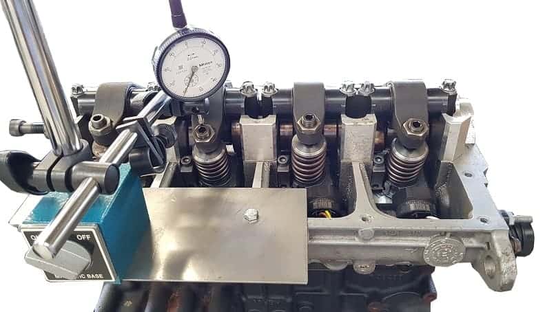
1. Dismantling rocker arm shaft.
To replace a unit injector, one of the two rocker shafts must be disassembled. In this case, the rocker arm shaft of the unit injectors of cylinders 3 and 4 has been removed.
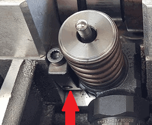
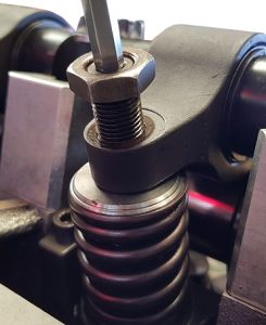
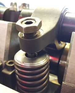
2. Remove the clamping block.
To remove the clamping block, the bolt (indicated with a red arrow) must be loosened. The clamping block is hooked into the atomizer and must be slid out.
3. Disassemble and assemble the unit injector.
Use the trigger to pull the unit injector from the cylinder head. Hook the protruding part of the trigger into the part where the clamping block hooks into the unit injector.
Install new O-rings around the injector before reinstalling. Then carefully press the injector into the cylinder head and fit the clamping block. Do not tighten the bolt yet, because then the atomizer can no longer be turned for adjustment.
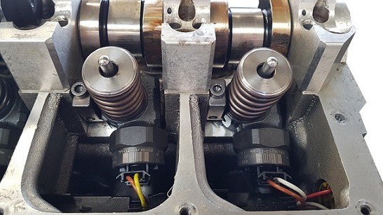
In the picture, the injector of cylinder 3 has been replaced (the left one). This one is visibly skewed. The adjustment is done in step 4.
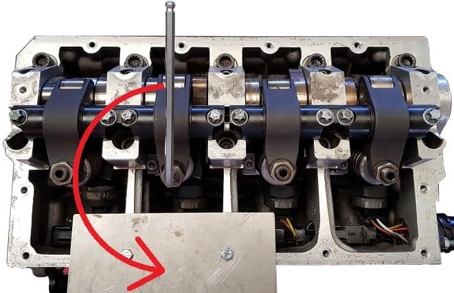
4. Adjust the position of the unit injector.
With the caliper the distance between the bulge of the atomizer and the outside of the cylinder head must be measured. This can be seen in the image.
If the measured value does not correspond to the value stated by the manufacturer, the atomizer must be turned. This will give the bulge of the atomizer a different distance to the outside of the cylinder head.
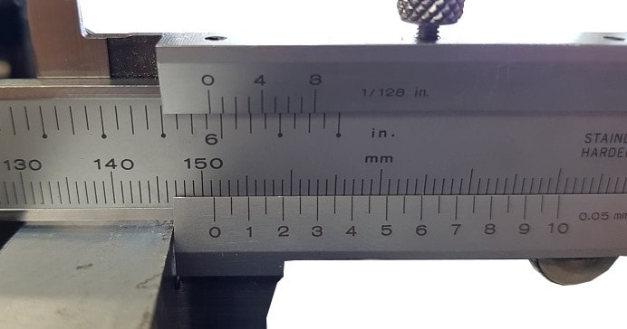
The prescribed value of this distance is: 151,3 mm ± 0,9 mm. This means that in the most ideal situation the size should be 151,3 mm, but that it may be deviated from 0,9 mm. The image below shows the measurement and the next image shows an enlargement of the reading on the ruler.
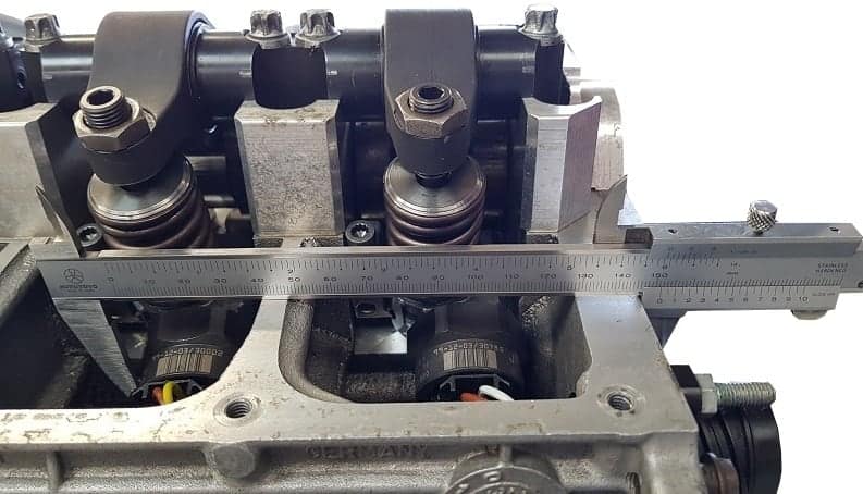
The figure shows an enlargement of the ruler with the measurement in step 4. The size indicated on it is 151,3 mm. This is the manufacturer's prescribed value. The bolt of the clamping block can Worden tightened.
The right measuring jaw of the caliper should be held on the cylinder head when measuring other unit injectors. The adjustment values of the other injectors will therefore all be different. In order to be able to carry out the measurement on the atomizer of cylinder 1 (distribution side), the caliper must have a measuring range of 400 mm.
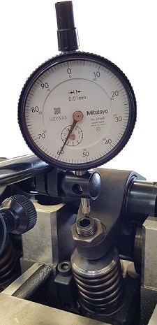
5. Fit the dial indicator.
Install the dial indicator on the injector that has been replaced. Rest the dial indicator on the side of the rocker arm that lowers when the unit injector is operated.
Because it is the intention that the needle of the dial indicator touches the rocker arm in all cases, the dial indicator must be pressed onto the rocker arm with a bias. When moving up and down, the needle will always hit the rocker arm. Make sure that the pre-tension is at least 3 mm.
6. Rotate the crankshaft until the rocker arm has reached its lowest point.
The purpose of this measurement is that the lowest point of the tumbler is measured. The measurements below are performed at the unit injector of cylinder 2.
When turning the crankshaft, the rocker arm will lower, so the value on the dial indicator will decrease. The hand will move back counterclockwise.
When the lowest point is reached, the pointer will stop. When turning the crankshaft further, the pointer will rise again. At the point in between, where the pointer stops, the rocker arm has reached its lowest point and the adjustment procedure must be followed.
7. Adjust the unit injector (1).
Loosen the locknut and then turn the adjusting bolt all the way up until the rocker arm touches the top ring of the unit injector.
8. Adjust the unit injector (2).
Turn the adjusting bolt into the rocker arm as far as it will go. The spring of the unit injector is thereby compressed. Turning can be tough. Stop turning when a lot of resistance is felt, because at that moment the piston in the unit injector touches the bottom of the high pressure chamber.
9. Turn the adjusting bolt back 180°.
Now that the adjusting bolt has been fully tightened to its stop, it should be turned back half a turn. This prevents the piston in the unit from hitting the bottom of the high pressure chamber each time the camshaft operates the unit injector.
If several unit injectors have been replaced, this measurement must be repeated for each injector. Please note that the adjustment instructions may differ per engine code or year of construction!
No rights can be derived from the above instructions and images.
Fuel supply pump:
The fuel supply pump is a vane pump with sprung partitions. This is placed between the fuel filter and the atomizers. The pump is driven by the camshaft. There is a pressure limiting valve in the pump that limits the pressure in the supply line to 7,5 bar. A valve is mounted in the pump that keeps the pressure on the return line of the unit injectors constant at approximately 1 bar.
Custom distribution:
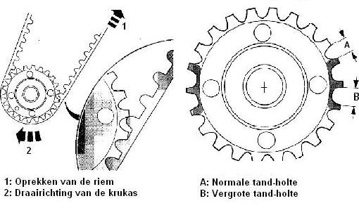
Because the pressure in the unit injectors can rise to approximately 2000 bar, the distribution of the engine is extra loaded. To prevent the belt from breaking, a number of measures have been taken:
- The crankshaft gear of the distribution has slightly larger tooth cavities in two places. The moment the unit injector builds up a high pressure, the timing belt will be stretched. This will increase the pitch of the teeth slightly. This is compensated by making the tooth cavities slightly larger in two places.
- The timing belt has been made wider, making it stronger.
Fuel cooler:
The fuel cooler's function, as the name suggests, is to cool the fuel. The fuel cooler is located near the radiator or under the car. There is continuous flow of fuel throughout the system. The fuel that returns to the tank is heated up considerably by the cylinder head of the engine. The fuel cooler cools the return fuel going back to the tank.
Related pages: