Subjects:
- Towbar
- Wiring
- 7-pin power strip (standard)
- 13-pin socket (without CAN bus)
- 13-pin power strip (with CAN bus)
- Auxiliary clutch and breakaway braking device
Towbar:
The towbar is usually retrofitted to the car. You can often choose between:
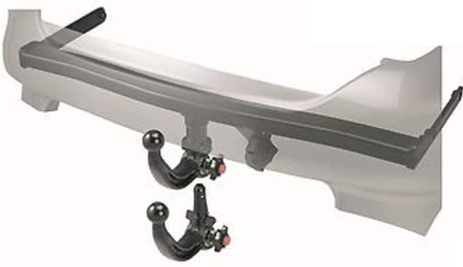
- A towbar with a fixed ball
- A towbar with detachable ball
- An electrically retractable towbar
The towbar with a detachable ball is most commonly fitted (see the picture). The towbar itself is often U-shaped and is screwed into the box girders of the car with the 2 ends. On other cars it may be a metal beam that is mounted only on the back of the box girders.
The mounting of the towbar is often quite simple. When the rear bumper is removed (and often also the rear light units), the steel bumper beam can be removed. The tow bar replaces this. This must then be attached to the body with 4 or 6 bolts (consult the manufacturer for the tightening torques, this is very important!) Note that there are cars where holes have to be drilled in the body parts yourself!
Enough space must be left for the tow ball, any button to be able to disassemble/assemble and of course the power strip. This must also be accessible. Connecting the cabling is often more difficult. This is explained in the next chapter.
Wiring:
When purchasing a towbar, you can opt for a 7-pin or a 13-pin socket. The difference is that the 13-pole has a constant and a switched plus, which is necessary to operate the refrigerator and the interior lighting in, for example, a caravan. This is described in detail (with the pin assignments and the colors) on the page terminal coding (socket socket).
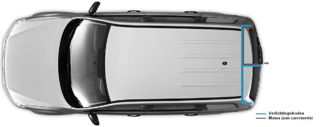
The images below provide insight into how the cabling runs from the standard 7-pin, the standard 13-pin or the 13-pin CAN bus towbar wiring.
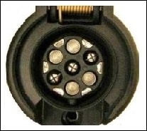
7-pin power strip (standard):
A wiring harness runs directly from the power strip to the rear lights. This is the simplest version. They are often ready-made sets that are specially made for a type of car, so that the plugs of the rear lights can be connected to the wiring set. The plugs of the wiring kit must then be mounted on the rear lights again. For example, the cabling does not have to be adjusted because only plugs are clicked together correctly. This cabling can be mounted very quickly and easily.
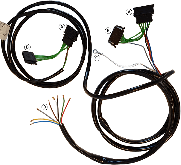
An example of such a standardized wiring harness can be seen in the figure below.
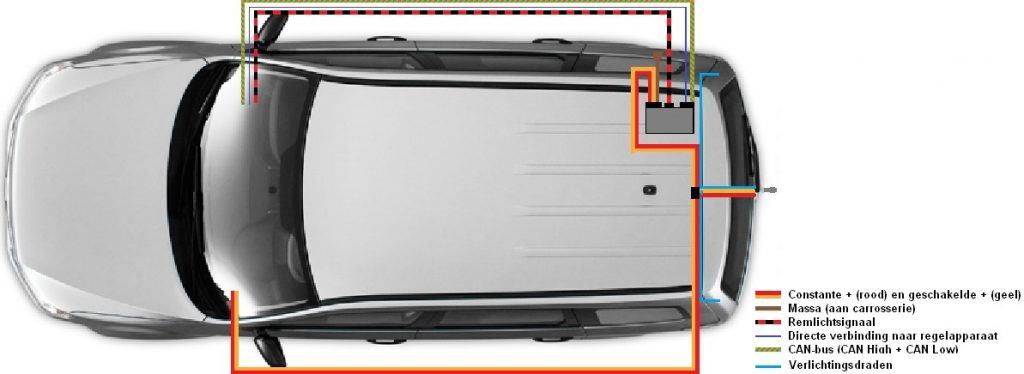
The image shows the wiring harness of a Volkswagen Polo 9N. This wiring harness is mounted between the standard plugs and the rear lights. Because the wiring harness is specifically designed for this Polo, all cables are of the correct length and the wires are in the correct positions in the plugs. Below is an explanation of what the designations A to D stand for:
- A: This is where the connectors of the rear lights are clicked in.
- B: These plugs snap into the taillights.
- C: This is the ground cable and must be mounted on a ground point on the body.
- D: These eight cables are for the 7-pin power strip. One wire has the function of switching off the rear fog lamp of the car when the cover of the socket is opened. From plug A, the voltages are looped through to both plug B (to the rear lights) and the wires to the socket (D). There is no constant or switched plus with this wiring harness. For this, a 13-pin socket must be mounted and two wires must be pulled here to the front of the car to connect them there in the fuse box.
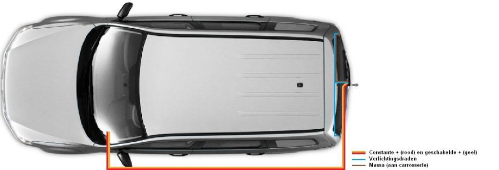
13-pin socket (without CAN bus):
From the power strip, cables run to the rear lights (as with the 7-pin). The rear lights control trailer lights directly. With a 13-pole socket there are also a constant and a switched plus present. These are connected to 12 volts via the fuse box (under the dashboard or otherwise under the hood). The constant plus always has voltage, and the switched plus only receives voltage when the contact is on terminal 15 (ignition on, or when the engine has started).
The cabling naturally runs along the inside (above the sill), but can also run forward via the right side. This depends on the vehicle type. In some cars, the cabling also runs under the car from the back to the front.
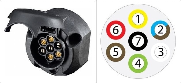
| 1. | L | Turn Signal Left | Yellow |
| 2. | 54G | Rear fog light (previously constant plus) | Brown / Blue |
| 3. | 31 | Sponge | White |
| 4. | R | Turn Signal Right | Green |
| 5. | 58R | Taillight, side marker Right, license plate light | Brown |
| 6. | 54 | Brake lights | Red |
| 7. | 58L | Taillight, side marker Left | Black |
NB! The pin assignments are standardized at the power strip. Wire colors may vary by manufacturer. View the correct installation manual or factory data for this!
13-pin power strip (with CAN bus):
The CAN bus version uses a control unit. This control unit controls the lighting (except the brake lights) of the trailer. From the BCM (Board Control Module, however each manufacturer has its own name) CAN-bus wires run to the control unit of the tow bar. Information is sent via these CAN bus wires which lighting should be on. An additional function of this CAN-bus system is that it is recognized when a lamp is defective on the trailer. A notification will be given to the driver. This is constantly monitored by the trailer control unit, just as is normally the case in a car with defective lighting these days.
The brake lights are controlled separately, so that if there is a CAN bus failure with the trailer control unit, the brake lights will function. The constant and switched positive wires are also present for the power strip. These now also serve as power supply for the trailer control unit.
The trailer control unit will always need to be coded by the brand's diagnostic equipment.
The 13-pin power strip can be designed as a Jaeger (the most common), or the Multicon. The Multicon West is a combination of a 7-pin and a 13-pin power strip. A 7-pin plug of a trailer can be mounted without any problems. Only the large, inner contacts are used (No. 1 to 7). In that case, the outer ones remain empty. There is no need to use an adapter plug. The outer contacts are only used if a 13-pin plug of the same type is connected.
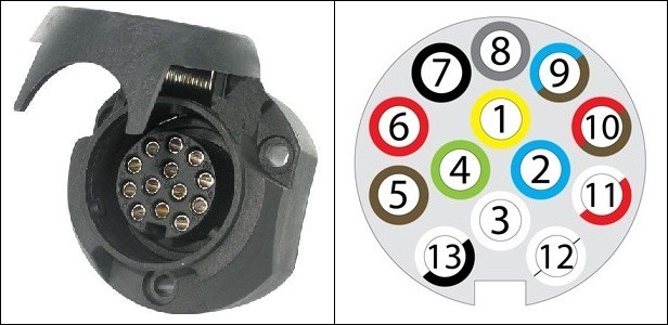
| 1. | L | Turn Signal Left | Yellow |
| 2. | 54G | Rear fog light (previously constant plus) | Blue |
| 3. | 31 | Sponge | White |
| 4. | R | Turn Signal Right | Green |
| 5. | 58R | Taillight, side marker Right, license plate light | Brown |
| 6. | 54 | Brake lights | Red |
| 7. | 58L | Taillight, side marker Left | Black |
| 8. | 8 | Reversing lights | Grey |
| 9. | 9 | Constant plus (e.g. for interior lighting) | Brown/Blue |
| 10. | 10 | Switched plus (for example battery or refrigerator caravan) | Brown/Red |
| 11. | 11 | Empty position (possibly ground) | White Red |
| 12. | 12 | Empty position | - |
| 13. | 13 | Sponge | Black and white |
NB! The pin assignments are standardized at the power strip. Wire colors may vary by manufacturer. View the correct installation manual or factory data for this!
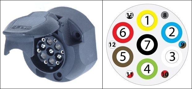
Multicon Feder:
The Multicon Feder is the predecessor of the Multicon West. The difference between these are the outer pin assignments; 8 to 13. With the Multicon Feder (see picture) these are flat contacts and with the Multicon West these are round pins.
The 'Feder' connection is no longer used these days, because it is more sensitive to interference than the 'West'. With this socket it is also possible to connect a 7-pin plug of, for example, a simple trailer or a bicycle carrier.
Auxiliary clutch and breakaway braking device:
In order to properly attach a trailer to the vehicle, it is legally required to use an auxiliary coupling or breakaway braking device. The moment the trailer comes loose from the towbar while driving due to a defect or an improper operation, a safety system must be present that then comes into effect.
For trailers with a maximum mass (of the trailer including the load) up to 1500 kg, the use of an auxiliary coupling is sufficient. An auxiliary coupling is nothing more than a thick steel cable that is attached to the trailer on one side and mounted on the car on the other side. If the trailer comes off the tow bar while driving, the cable will ensure that the trailer continues to follow the car. The auxiliary clutch does not operate the trailer brake.
If the maximum mass of the trailer exceeds 1500 kg, it must be fitted with a breakaway braking device. The breakaway brake device consists of a steel cable that applies the handbrake of the trailer as soon as it is released from the towbar while driving. The steel cable is thinner in this case than with an auxiliary coupling; the cable must break at a certain pulling force after the handbrake is applied. The trailer then brakes independently without being connected to the car. It is not allowed to have both an auxiliary coupling and a breakaway braking device on one trailer. In an emergency situation, the wheels of the trailer would lock due to the breakaway braking device while it is being pulled by the car with the auxiliary coupling.
The images on the right show four options for attaching the auxiliary clutch and the breakaway brake device. The cable must at all times be connected to a fixed part of the towbar or the body of the car. In picture 1 a special bracket is mounted on the tow bar. The cable must be laid in a loop in the bracket.
In pictures 2, 3 and 4 the cable is attached to a fixed point on the car body. This fixed point can also be a hole in the towbar bracket where the ball is mounted. Here too, an extra loop can be placed around the tow ball, as shown in figure 4. It is prohibited to lay the cable in a loop over the towbar ball, without this cable or loop being connected to a fixed part of the towbar or the bodywork. The fine is currently more than 150 euros.
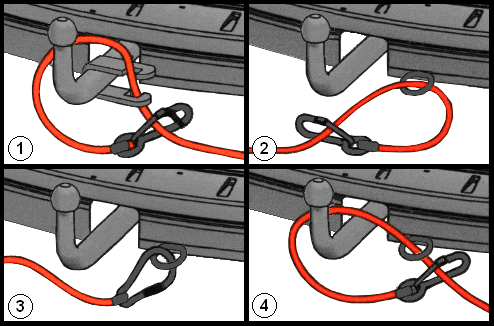
In cars with an (electronically) folding towbar, it is often not possible to mount a bracket as shown in figure 1 above. The towball ball often has a different shape; it is often square or rectangular in shape. Often there is an eye on the ball itself in which the cable can be mounted, but experience shows that this is not always the case. The manufacturer, in this case also the dealer, can supply attachments that fit the relevant tow ball. Inquire about this with the brand dealer.
When installing the cable, make sure that it cannot touch the ground while driving, even if the car is going to collapse at the rear. Damage to the cable leads to an unreliable protection system.