Subjects:
- General
- Steering column
- Direct wheelhouse
- Indirect wheelhouse
- Variable Gear Ratio
General:
The steering system of a car is very complex. Steering movements must be correctly transferred to the road surface; without play and without heavy points during steering. This page explains what types of steering systems exist and how the power steering is applied to the steering box. The operation of the power steering is shown on the page power steering described.
Steering column:
The image below shows the complete steering system of a car. The part between the steering wheel and the flexible rubber cover is mounted in the dashboard. Usually this is covered with plastic caps and is not visible. The steering movements are transferred via the steering column to the steering axle. The steering shaft is mounted on the steering box; this is explained further down this page.
It is often not possible to apply a straight axis between the steering wheel and the steering column, but there are one or more bends in it. This can also be seen in the image below. A universal joint is mounted at the height of the flexible rubber cover, which makes it possible to transfer the steering movements at a certain angle from the steering column to the steering shaft. The flexible rubber cover has the function of sealing the hole in the bulkhead where the steering column or steering shaft passes from the interior to the engine compartment. The cover ensures that engine noises and heat cannot escape from the engine compartment to the interior. If squeaking noises are heard while steering, the steering axle in the cover may be squeaking. This may be remedied by applying a small amount of lubricant.

The steering column in the picture above is adjustable. By unlocking the adjustment lever, the complete steering column (depending on the vehicle version) can be moved up and down, pushed in and pulled out. The latter is possible because a large part of the steering axle consists of 2 axles that are mounted on top of each other and can therefore shift from each other in the longitudinal direction. This is done at the steering column in the picture in the area between the adjustment lever and the flexible rubber cover. The underside of the steering shaft is connected to the steering box. This will be clarified further on on this page.
Direct wheelhouse:
The picture shows a direct wheelhouse. The steering column drives the steering shaft by means of two universal joints. The steering shaft is connected to the rack and pinion of the steering box; here the rotational movement of the steering axle is converted into a reciprocating movement to the tie rods. The wheelhouse is on the subframe confirmed. The track rods push against the ends of the steering knuckles of the wheel suspension. Because the pivot points of the knuckle pieces are in the middle, a rotating movement will take place. This movement turns the wheels.
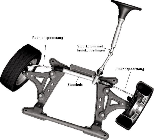
The picture shows the connection between the rack and the steering box. At “Axle attachment point from steering column” a metal bracket grips over this axle. This bracket is attached to the steering shaft with a bolt in the bolt hole. Because there is a single recess, the steering axle can only be mounted in one way. Make sure that the steering wheel is not turned completely after installation, because then the slip ring of the steering airbag will break.

When the steering wheel turns to the left or right, the steering shaft rotates over the rack and pinion on the steering rack. The steering shaft remains in a fixed position and the rack and pinion rotates from left to right. This angled transmission ensures that the wheels can turn from left to right. In the image below under “Steering axle connection” the rack and pinion shaft of the previous image can be seen as it actually is.

Two hydraulic lines can be seen on the steering box (in the picture above below the connection of the steering shaft). These lines are from the power steering. On these lines there is a constant oil pressure which is provided by a plunger pump (called the power steering pump, or servo pump). This pressure is on both sides of the steering rack and ensures that the steering movements are reinforced.
More about this on the page power steering.
Indirect wheelhouse:
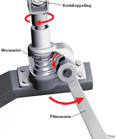
An indirect steering box is equipped with a pitman arm and an auxiliary pitman arm. A steering rod is mounted between these pitman arms, which transfers the steering movements from the pitman arm to the auxiliary pitman arm. The indirect wheelhouse is on the subframe confirmed. The image shows an indirect wheelhouse.
In contrast to the direct steering box, the steering movements are not transmitted to the rack and pinion via the steering shaft, but via a worm wheel to the pitman arm. The worm wheel will rotate during steering movements, so that the gear on the shaft of the pitman arm will rotate with it. This moves the pitman arm.
In the figure below, the steering movement is indicated by arrows.

Variable Gear Ratio:
A steering box may be designed with a variable transmission ratio. When the steering wheel is in the straight ahead position, the tines are close together. Steering wheel movements therefore cause a small steering movement of the wheels. This is very pleasant when driving straight ahead, because the driver does not have to correct much.
When the steering wheel is turned further, it will reach the teeth that are further apart. Therefore, the same steering movement of the steering wheel will cause a greater steering movement of the wheels. This makes parking easier, among other things, because the steering wheel does not have to be turned as far up to the maximum steering stop.

Related pages: