Subjects:
- Seiliger Process
- PV diagram of a gasoline engine (Ottomotor)
- PV diagram of a diesel engine
- Theoretical vs. real circular process
Seiliger Process:
The Seiliger process is a circular process for the combustion of an engine. Both the diesel and the petrol engine are based on this, but the final pressure development differs; the diesel is a constant volume process and the petrol engine a constant pressure process.
The Seilinger process comes straight from thermodynamics. During the compression of the air, the pressure increases and the volume decreases (the compression stroke). During the power stroke, the volume increases. The volume decreases on the exhaust stroke. The Sankey diagram is determined by means of the Seiliger process.
Seiliger Process:
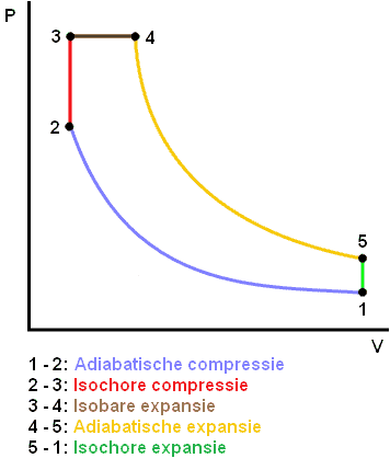
1 - 2: Adiabatic Compression: There is no heat exchange with the environment. The piston compresses the mixture without heating the material. All heat now remains in the mixture. (Compression stroke)
2 - 3: Isochoric compression: The volume remains the same and the pressure increases. This is still the compression stroke.
3 - 4: Isobaric expansion: The pressure remains the same and the volume increases (Labor stroke).
4 - 5: Adiabatic Expansion: Again there is no heat exchange with the environment. The piston moves downwards again (working stroke).
5 – 1: Isochoric expansion: The pressure decreases at a constant volume (Exhaust stroke and Inlet stroke).
- Adiabate: No temperature exchange with the environment, the process is reversible.
- Isochore: Volume remains the same.
- Isothermal: Temperature stays the same.
- Isobar: Pressure stays the same.
- Isentropic: Reversible process.
The adiabatic compression is often described in books and on websites as the isentropic compression. Because the gas cycle in the combustion engine occurs so quickly (by means of the intake compression work power strokes) there is almost no time to exchange temperature with the materials of the engine during the compression stroke and the power stroke. Therefore, it is better described as an adiabatic compression and expansion. So on this page no isentropes, but adiabates are mentioned.
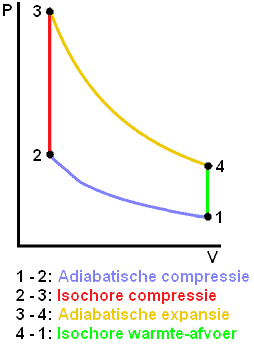
PV diagram of a gasoline engine (Ottomotor):
The PV diagram of a gasoline engine can be described as an equal volume process. In the adiabatic compression (from 1 to 2) there is no heat exchange with the environment. That is the case with the isochoric compression (2 to 3). The material of the motor will heat up as a result. This is not the case with a diesel engine. This is also the reason why the petrol engine reaches operating temperature faster than a diesel engine. The efficiency of a petrol engine decreases partly due to the isochoric compression. The adiabatic expansion and the isochoric heat dissipation are almost equal in a petrol and diesel engine.
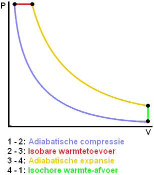
PV diagram of a diesel engine:
Because combustion in a diesel engine is gradual (by means of several injections) so that the pressure does not change with an increasing volume.
The isobaric heat input (2 to 3) is the combustion of the fuel. The area of the diagram (ie the area between the lines) of a diesel engine is larger than that of a petrol engine. The efficiency of a diesel engine is therefore also higher.
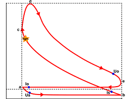
Theoretical vs. actual circuit process:
The Seiliger / PV diagram are of ideal gasoline and diesel engines. In reality, the pressures and volumes are different because there are always non-ideal gases and losses. The actual circular process is shown in the indicator diagram to display.
Related pages: