Subjects:
- BMW engine
- First work of the project
- Checking the oil pump
- Remove from distributor
- Start – and charging system
- Frame with monitors and computer
- Dashboard with electrical installation
- Cooling
- Fuel tank
- Air Intake Tube, Air Filter, Crankcase Breather Hoses
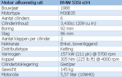
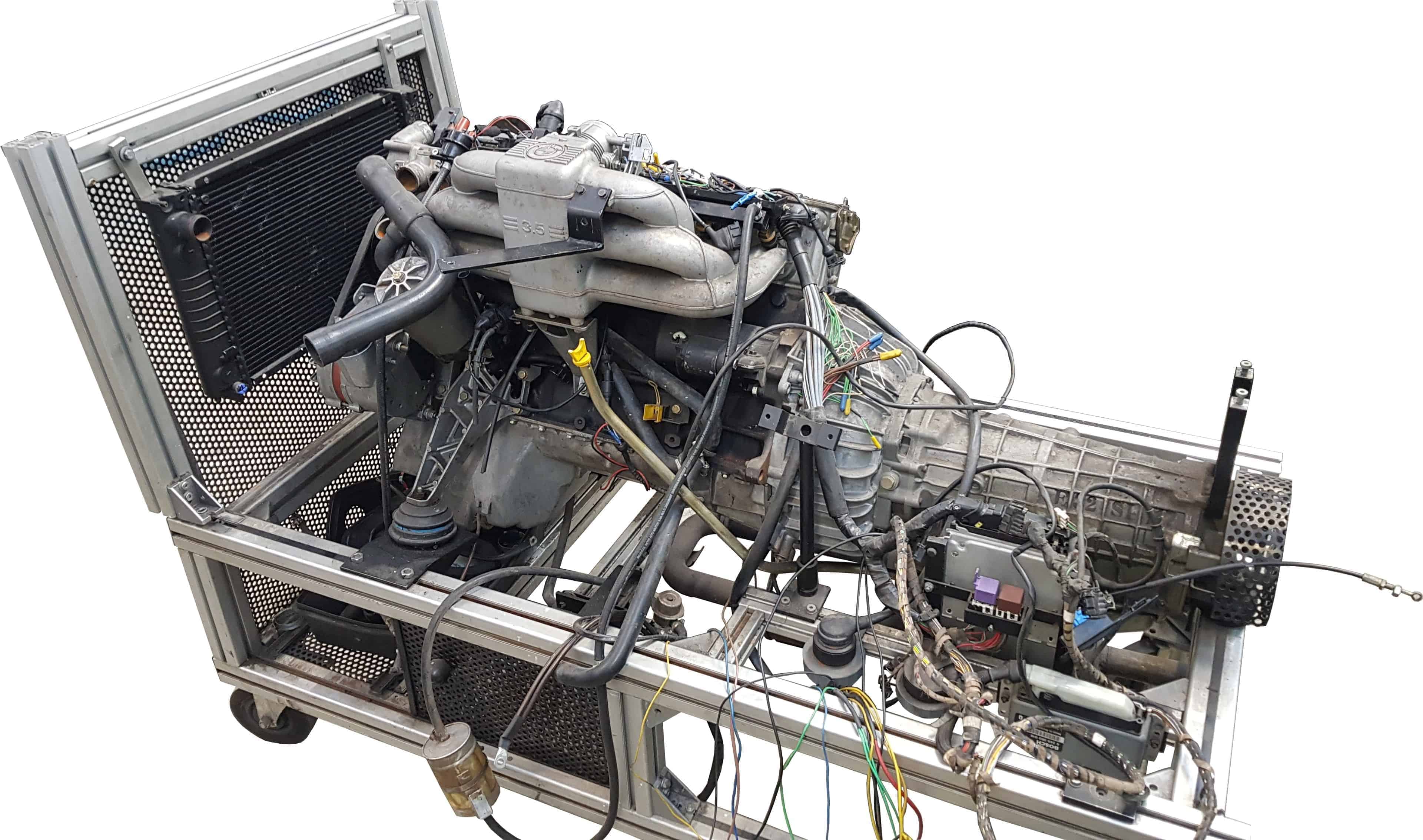
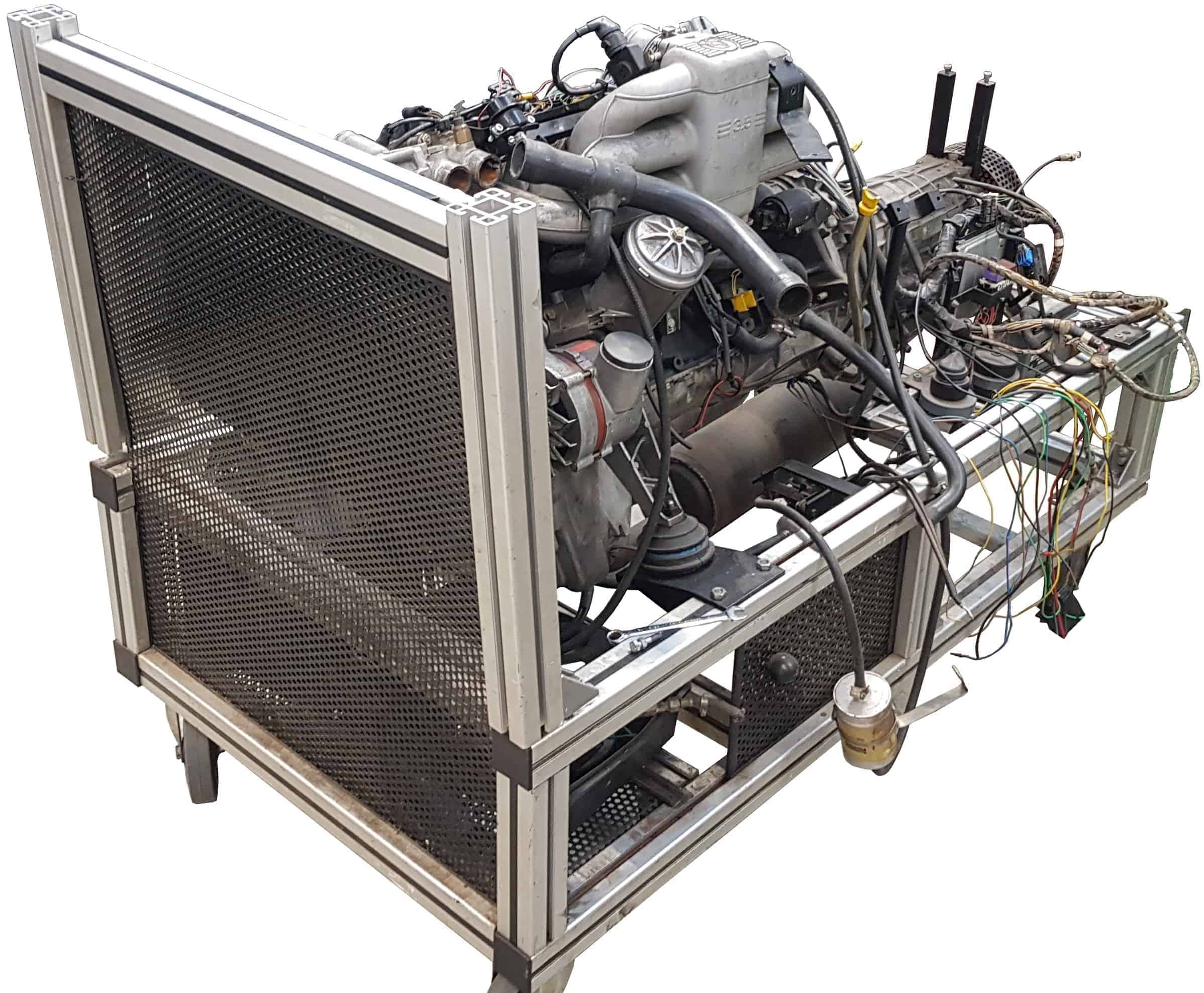
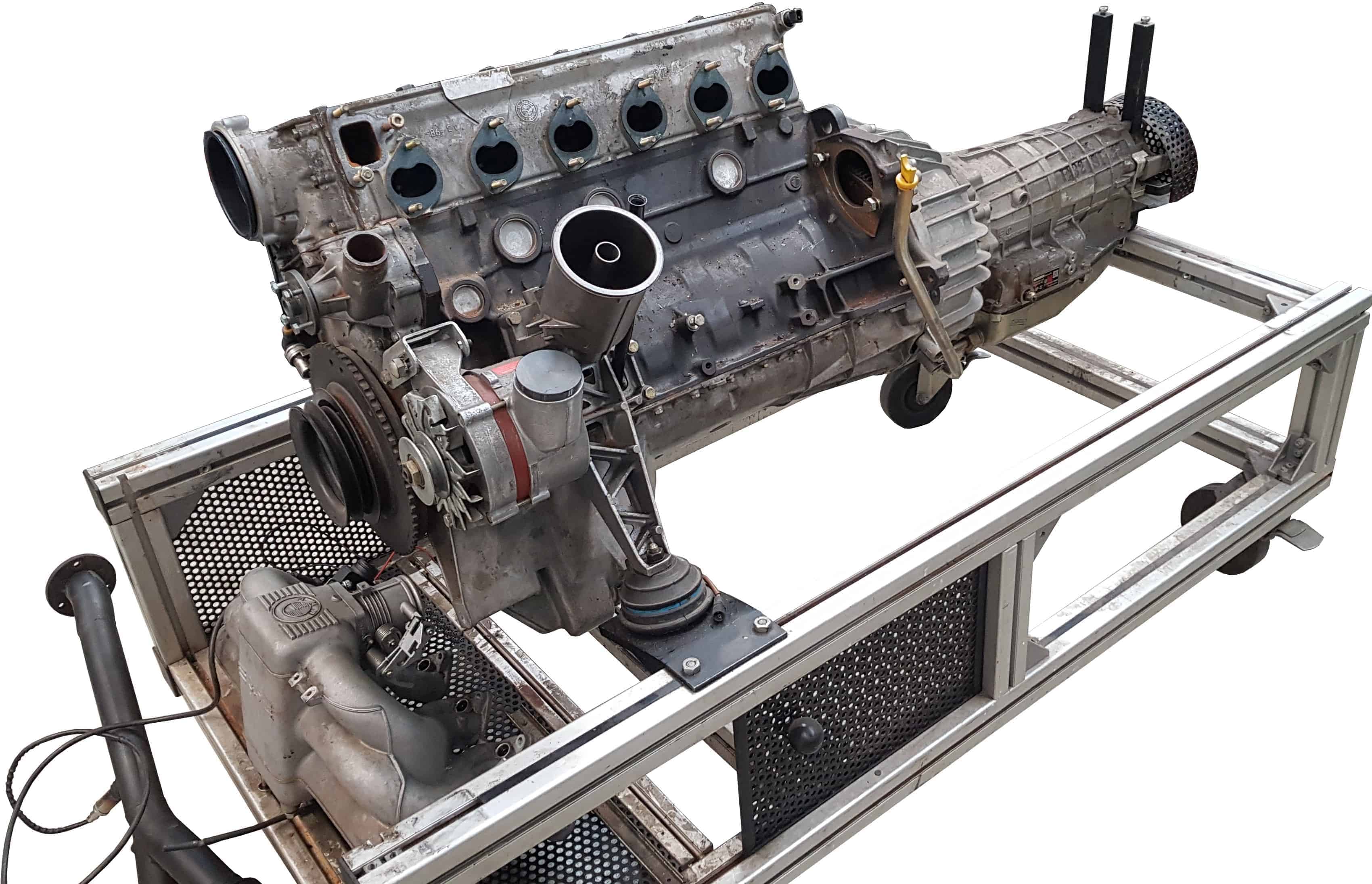
BMW engine
The choice to use this BMW engine for this conversion project was an easy one; there was too much defect for students to work on, but still good enough to fix up. The engine comes from a BMW 5-series E34. The table below shows the engine data.
The first activities of the project:
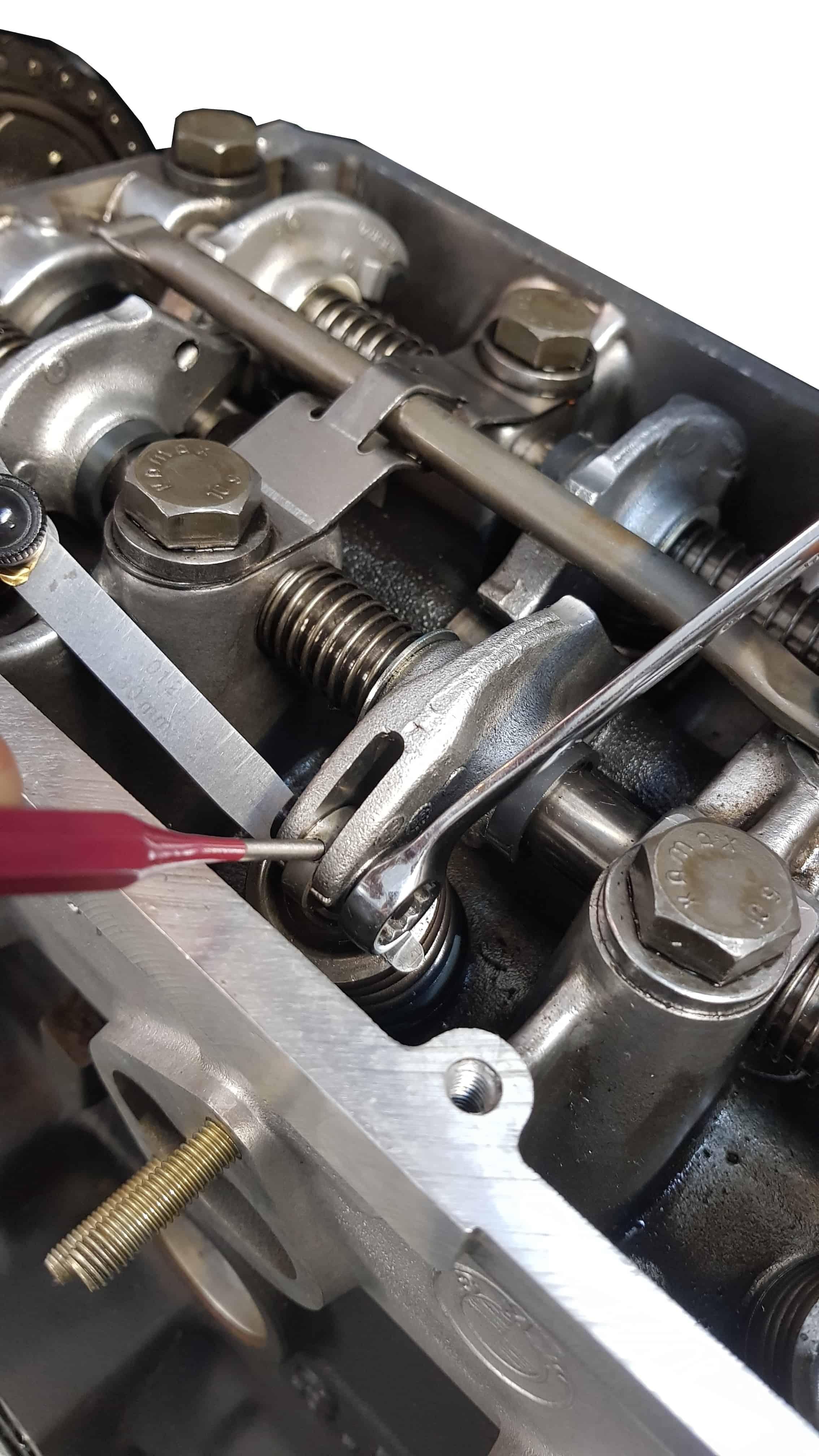
As stated before, the BMW engine is in good condition. A highly motivated student immediately set to work removing attachments. The wiring harness, original ECU and ODB1 diagnostic plug are permanently removed. Other parts such as the valve cover, the manifolds incl. exhaust, frame with radiator are checked, cleaned and later reassembled with new gaskets, O-rings and hose clamps. The valves are adjusted, the coolant pump is replaced preventively due to age and rust.
Naturally, the oil is changed and the cooling system is cleaned. At a later stage, when the engine has been running for at least an hour, the fluids are refreshed again and the filters replaced.
The photos below show the beginning of the project with the attachments being disassembled and the valve clearance adjustment. Click on the photos to open them in full size.
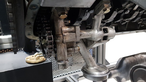
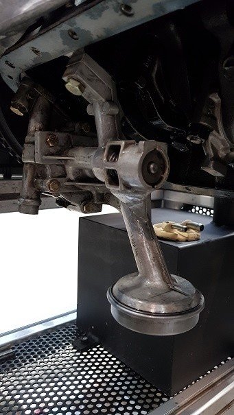
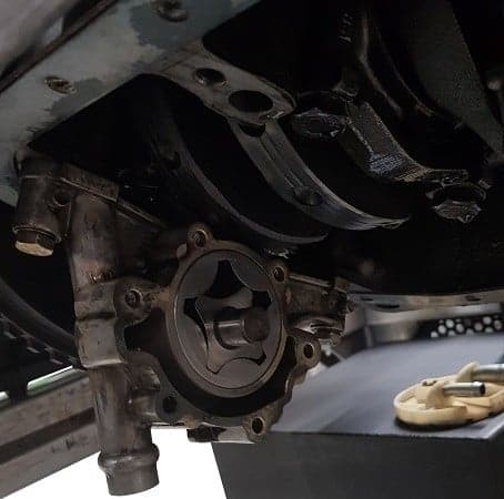
Checking the oil pump:
During the actuation of the starter motor, the oil circulation in the cylinder head was taken into account. During the start there was no oil supply to the camshaft etc. It was not known whether the oil pump and suction strainer were in order; after all, the engine has been used for practical assignments in the past. There may be something missing from the oil supply. It was therefore decided to disassemble the oil sump and to check the oil pump and strainer.
After disassembly and checking, we concluded that the oil pump and accessories were in order. The parts have been reassembled and the oil has been topped up again.
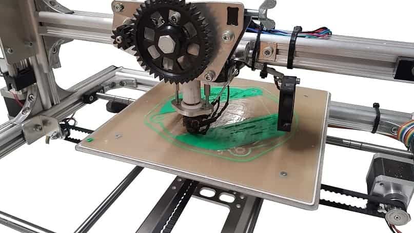
To remove the distributor:
The ignition system is equipped with a DIS coil. We remove the original ignition coil and distributor. Removing the distributor left an uncovered hole in the cylinder head. This shows the end of the camshaft and the camshaft seal. At a later stage, a camshaft position sensor can be fitted here, in combination with a MegaSquirt III (for the time being, we use the MS-II). In order to cover the whole neatly, a cover plate was drawn using AutoCAD and created with a 3D printer. The photo was taken 10 minutes after printing started. In total, printing took 3,5 hours.
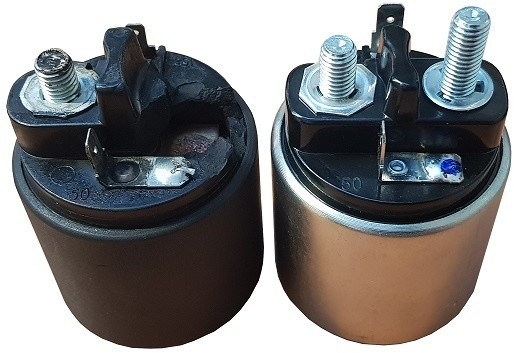
Starting and charging system:
One of the visible defects was a defective starter relay. At least, the threaded end has broken off. Repairing the starter relay seemed impossible. Fortunately, the costs turned out to be not too bad: for €25, the local overhaul specialist supplied a new starter relay. The picture shows the broken one (left) and the new one (right).
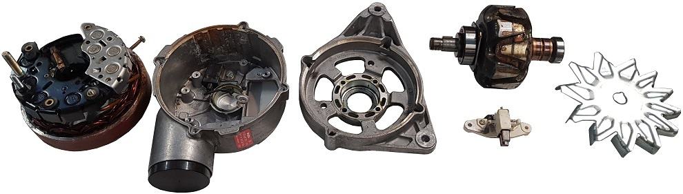
We had less luck with the dynamo. After connecting the positive wires, while connecting the ground wire, it was discovered that there was a short somewhere in the system. After a short search, the cause was found; the B+ of the alternator made contact with the housing. The resistance between the B+ and the housing was 0,2 ohms. The dynamo was immediately disassembled and opened. What turned out? The D+ connection made contact with the housing because the interior was not straight in the housing and the plastic bush was broken. The dynamo has never been able to function in this way; presumably a student has taken the alternator apart in recent years, after the engine has stopped running, and has not reassembled it properly.
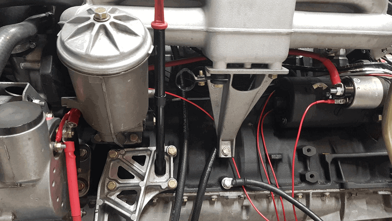
After repair of the starter motor and alternator, the wiring has started. The red wires can be seen in the picture below.
The positive wire from the battery is connected to the B+ connection of the dynamo. The plus wire to the starter motor is also mounted on this same stud.
The D+ wire on the alternator is connected to a fuse (terminal 15) via the charging current indicator lamp on the dashboard. The starter motor control wire (terminal 50) is operated by the start button on the dashboard.
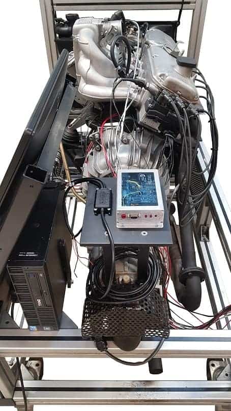
Frame with monitors and computer:
A desktop computer with two monitors is mounted on the engine frame. These screens will eventually show the meters of the dashboard and the fields. It is also possible to demonstrate measurements with an oscilloscope (Picoscope) on a screen.
The frame has been processed in such a way that the two screens can be mounted one below the other. The screens are tilted at a certain angle, so that they can be clearly read when standing in front of the motorcycle.
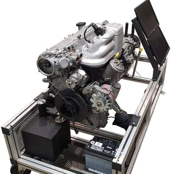
The desktop computer is placed behind the screens on the motor frame. The PC is of the brand Dell and type Optiplex XE (Core2Duo 2,6 GHz, 4 GB RAM). This type of computer is designed to run 24/7 under heavy duty business applications such as hot, dusty areas. This PC is therefore extremely suitable to function on the engine frame while the engine is running. The standard hard drive has been replaced by an SSD to minimize the risk of vibration. The PC and displays are sponsored by Zenid.net.
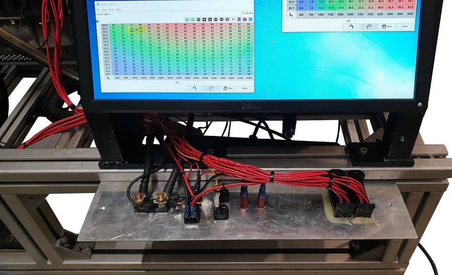
Dashboard with electrical installation:
A panel with a number of components is mounted under the screens. The picture shows the back of the panel with the wiring.
From left to right:
- Ground breaker switch
- Ignition switch (terminal 15) and start button (terminal 50)
- Cooling Fan Switch
- Lamp clamp 15
- Charging current control lamp D+
- Fuse box 1 (6x)
- Fuse box 2 (6x)
The electrical scheme has recently been changed. The new version will be added to this page shortly.
Cooling:
The original parts of the cooling system were incomplete, dirty and/or defective. In addition to a new coolant pump that has been replaced preventively, the following parts have also been newly installed:
- Radiator;
- coolant reservoir;
- Six new radiator hoses;
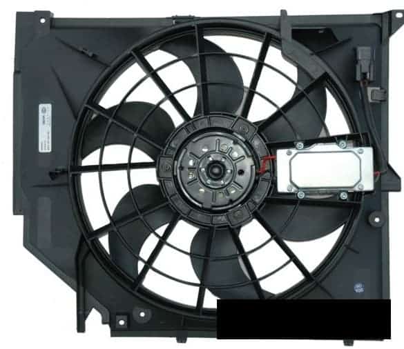
- Cooling fan.
These components are not from an E34, but an E46 (3 series). The size of the radiator, the diameter of the cooling hoses and the power of the cooling fan are sufficient to achieve good cooling. The cooling fan has a power of no less than 390 W.
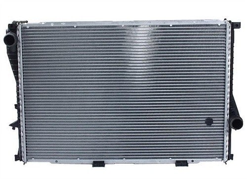

The above images show the radiator and expansion tank. These components belong together; the reservoir can be attached to the radiator at the top and bottom. This requires a special frame that is in between. This frame is not pictured.
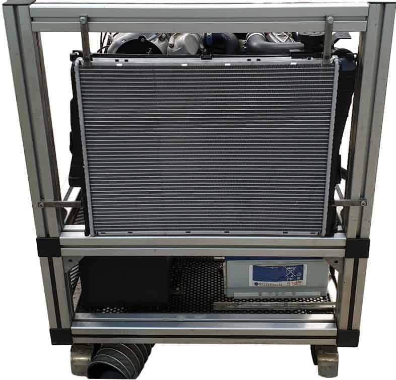
The image below shows the cooling fan. The fan also belongs to the radiator and reservoir; these three parts are attached to each other. The image below also shows the time when the cooling components, consisting of the components just described, were hung in the frame. In this way the height and the distance between the thermostat housing and the tube of the reservoir could be adjusted. Finally, an S-shaped cooling hose comes in between.
The radiator is mounted as follows:
- rubber blocks are fitted between the radiator and the horizontal bar of the engine frame, so that the radiator can stand on them;
- thanks to the iron bars on the left and right, the radiator is clamped in all directions;
- The iron bars at the top ensure that the radiator cannot tilt.
A cooling hose with the original dimensions is fitted as standard on the flange that is clicked onto the top of the radiator. The bends in the hose do not match the space we have available with this engine. That is why the standard cooling hose has been removed from the flange and the ring that was shrunk around it was ground off. Instead, two hoses with a diameter of 38 mm (G4278-17033) have been cut to size and mounted in an S-bend.
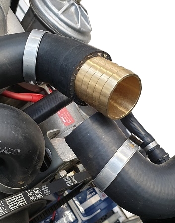
A good confirmation of the two hoses was sought for a while. Plastic PVC pipe turned out to be too soft and deformed with hot coolant, so was unsuitable. The auto parts store went looking and eventually came up with a brass hose connector (WK 34305) that fit perfectly. Thanks to the ribbed exterior, the hoses clamp perfectly.
The picture below shows the brass hose connector that is half contained in one cooling hose. The other cooling hose is also mounted on the hose connector and the hose clamps are firmly tightened.
The same type of hose connector is also mounted between two other cooling hoses on the underside of the radiator.

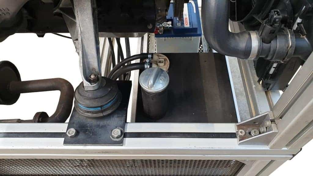
Fuel tank:
The fuel tank with a capacity of 20 liters was already in the same place in the old condition. The tank is attached to the engine frame and is located in the corner, next to the battery, under the lower radiator hose. An original chrome cap closes the tank.
The image below shows the fuel tank and the two fuel hoses. One is the supply and the other the return. The hoses run to the fuel rail, where the injectors are mounted. These components are described in the chapter “actuators”.
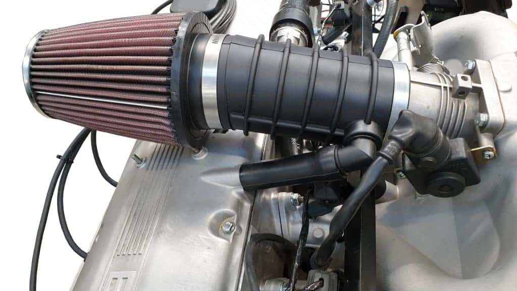
Air intake tube, air filter, crankcase breather hoses:
The original air intake tube, crankcase breather hoses, PWM idle control valve and air filter housing were missing. Even though a number of parts would have been present, there was a good chance that there were cracks due to age and frequent disassembly/assembly. These parts have been purchased new, except for the PWM control valve. The air intake pipe and crankcase breather hoses were ordered from a BMW dealer. The original air filter housing would not fit neatly on the engine frame, so the choice to mount an open air filter was quickly made. The air filter (K&N, KNRC-3250) had the same diameter as the air intake tube.
Using AutoCAD a 3D printer, an attachment was designed and printed that could be mounted between the air filter and the intake pipe.