Subjects:
- Potentiometer
- Resistance course
- Signal voltage
- voltage divider
- Potentiometer for mirror adjustment
- Throttle Actuator Potentiometers
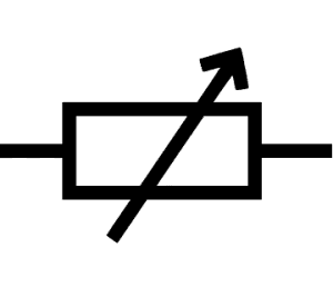
Potentiometer:
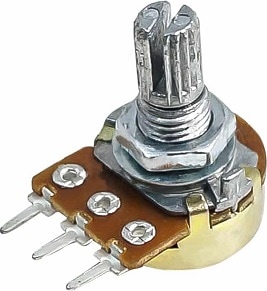
A potentiometer is also called a potentiometer or angular displacement sensor and is often used in automotive engineering as a position sensor for, for example, the accelerator pedal, the throttle valve or for the tank level. The runner (sliding contact) moves over the carbon track by means of an adjustable part, where a resistance change is obtained by which the position can be determined. The three images below show an actual potentiometer, the parts in a potentiometer and the symbol of a potentiometer.
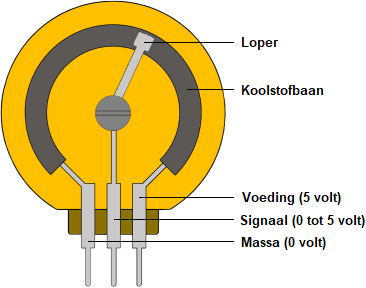
The resistance of the signal connection changes when the cursor is rotated to a different position on the carbon track. However, a control unit cannot “read” a resistance. A control unit applies a reference voltage of 5 volts and a ground to the two outer terminals of the potentiometer. Because current flows through the carbon track, the voltage of 5 volts in the carbon track is consumed. A voltage of 5 volts prevailed at the input and 0 volts at the output. Halfway through the carbon path, half the voltage has been consumed: here the voltage is therefore half the reference voltage, ie 2,5 volts. The voltage sent to the control unit via the wiper and signal terminal provides the control unit with sufficient information to determine the position to the nearest degree. This is used for the accelerator and throttle position sensors.
The voltage of 5 volts is a commonly used value because the onboard voltage remains above 5 volts during all operating conditions. If important sensors were to operate with a voltage of 12 volts, they could malfunction when the engine is started: the starting voltage in winter with a moderate battery can drop to 10 volts.
Another possibility is that the potentiometer supplies a voltage for an electrical circuit with e.g. an opamp, as with the headlight adjustment. In that case, the potentiometer works with a voltage of 12 to 14 volts.
The potentiometer can often make a 270-degree turn. We assume here a potentiometer with a linear gradient. The animation shows the output voltage at seven different positions of the runner:
- 0 degrees: 0 volts
- 45 degrees: 0,8 volts
- 90 degrees: 1,7 volts
- 135 degrees: 2,5 volts
- 180 degrees: 3,3 volts
- 225 degrees: 4,2 volts
- 270 degrees: 5 volts
In reality, the output voltage changes with every degree of rotation of the wiper across the carbon track:
- The total stroke is 270 degrees;
- The resistance is 10 kΩ (10.000 Ω)
- With every degree of rotation, the resistance changes by 37 Ω
- The voltage changes by 18,5 mV (0,0185 V) with every degree of rotation.
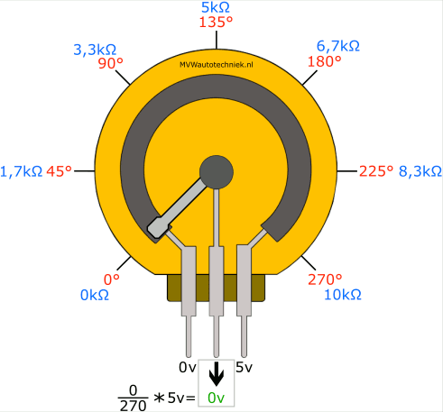
In the animation above we see that at 0% rotation the signal voltage is 0 volts and at 100% 5 volts. However, this can also be the other way around: 0% twist 5 volts and 100% 0 volts.
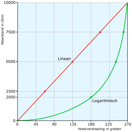
Resistance course:
With a linear potentiometer, each degree of angular displacement corresponds to a certain fixed value. For example, a 270 Ω potentiometer that can make a stroke of 270 ° gives 1 Ω resistance difference per degree of rotation. With a logarithmic potentiometer, the resistance change is not directly proportional but progressive.
In the following image we see the linear gradient (red) of the potentiometer in the previous section. In addition, the logarithmic course (green) of the other type of potentiometer can also be seen. The logarithmic potentiometers are mainly used to simulate physical processes.
The signal voltage of these potentiometers is proportional to the resistance.
Signal voltage:
The potentiometer is switched in the following way:
- Supply voltage of 5 volts from the control unit;
- 0 volt ground through the control unit;
- The wiper passes the analog voltage from 0 to 5 volts to the signal terminal of the control unit.
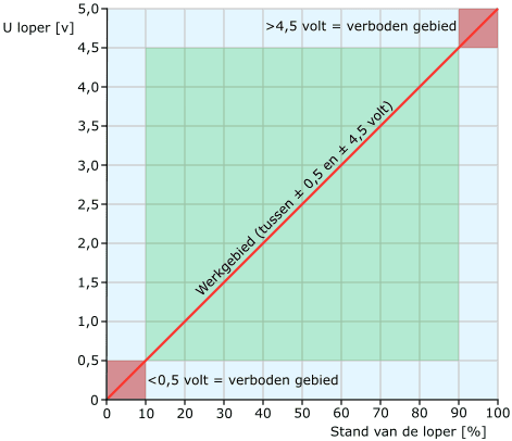
The working range of the potentiometer is between 0,5 and 4,5 volts. Manufacturers can also choose other extreme values, for example: 0,4 to 4,6 volts. The signal from the potentiometer must never extend beyond this working range. If the Control Unit detects that the signal voltage is in the forbidden area, it recognizes it as faulty and stores an error code.
- Signal voltage 5 volts: indicates an interrupted ground wire or positive circuit;
- Signal voltage 0 volts: Indicates an open supply wire or ground fault.
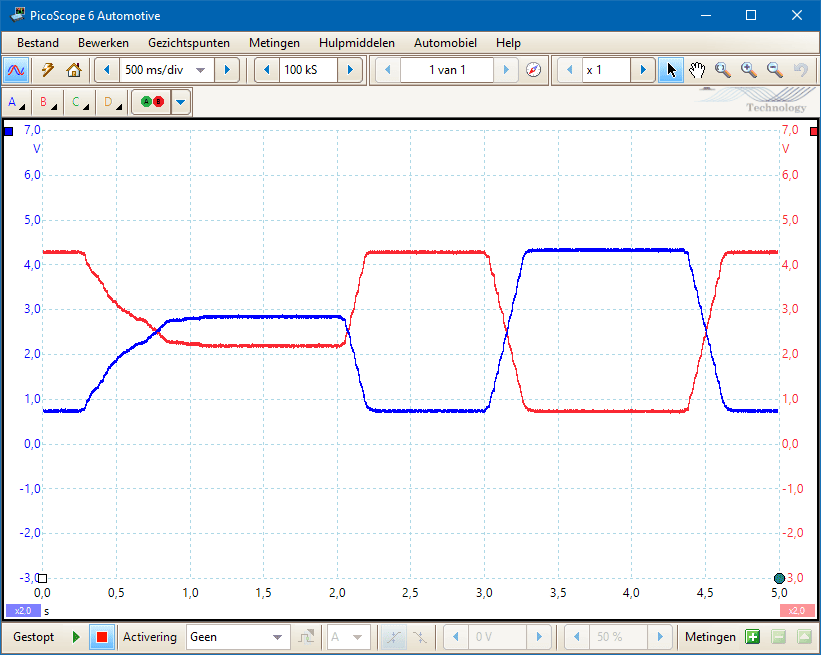
In order to guarantee the reliability of the signal, a double potentiometer is used with an accelerator pedal or a throttle valve. The signals can be mirrored vertically relative to each other (as shown in the figure), or proportionally at a different voltage height. In any case, they should not be equal to each other. The ECU compares the signal voltages.
The moment the ECU detects a signal on one of the two potentiometers that is unreal (spikes, or the signal ends up in the forbidden area), it goes into the so-called emergency mode and uses the second signal.
On the page: accelerator pedal and throttle valve The application of the potentiometer is extensively discussed, including “throttle by wire” and scope images of signals with errors.
See also: sensor types and signals.
Voltage divider:
A series circuit consisting of resistors behaves like a voltage divider. The supply voltage is distributed over the resistors in this series connection resp. voltage divider. The smallest resistance has the smallest voltage drop and the largest resistance has the largest voltage drop.
The figures below show the potentiometer in real situation and in schematic representation, which is connected to a voltage source of 12 volts. The wiper of the potentiometer is halfway. In the middle image we see the potentiometer in schematic form. On the right we see the voltage divider with two separate resistors with connection 3. The three diagrams are equivalent to each other.
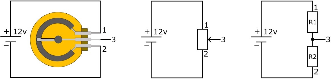
Since the potentiometer has a fixed resistance value, the sum of the resistances (R1 + R2) is equal to the total resistance. The movement of the bishop causes a resistance change of R1 and R2 (right diagram). The output voltage on pin 3 is high when the wiper is at the top and the resistance value R1 is small.
Potentiometer for mirror adjustment:
Two electric motors provide horizontal and vertical adjustment options for the mirror glass. In modern vehicles, the control takes place via a control unit. The diagram below shows this control unit (J386). The control unit activates the servomotor as soon as:
- the driver operates the mirror adjustment button, or:
- reverse gear is shifted and a mirror glass has to be pointed downwards (usually the one on the co-driver's side);
- must be moved to another desired position by the memory function. Usually this is identified by the key (remote control);
- the technician controls the actuator by means of an actuator test by means of a readout computer.
To get the mirror glass in the desired position, it is necessary to recognize the position of the mirror glass. Potentiometers G791 and G792 send the signal to the control unit via the gray/yellow and blue/red wires. As soon as the mirror positions of two different drivers are stored on their own key number, the servomotor adjusts to the correct position as soon as the relevant driver unlocks the doors with the remote control. In addition to the correct mirror glass positions, usually (if present) the electric steering column adjustment and seat position adjustment are also set in the set position. On the page: exterior mirrors and mirror adjustment the control methods of the mirror adjustment motors are described.
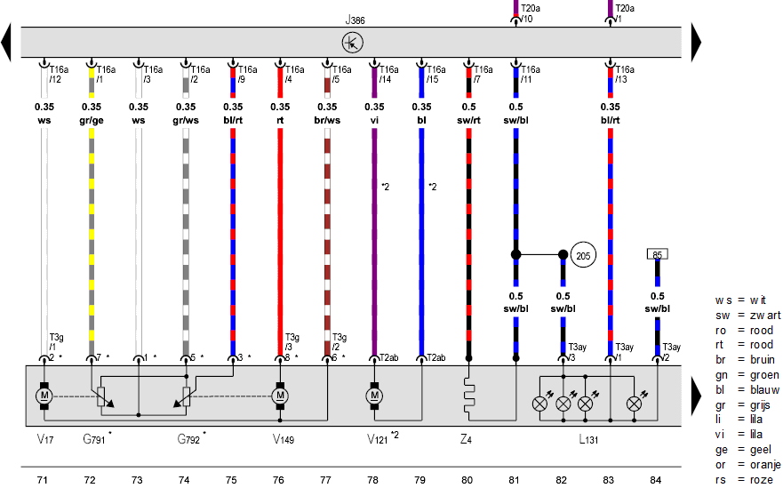
Description:
- J386: door control unit;
- V17: motor for horizontal mirror glass adjustment;
- G791: potentiometer horizontal mirror glass adjustment;
- G792: potentiometer vertical mirror glass adjustment;
- V149: motor for vertical mirror adjustment;
- V121: motor mirror folding function;
- Z4: mirror heating element;
- L131: Flashing light bulbs in exterior mirror housing.
In the above electrical diagram electric motor V121 (mirror folding function) can also be seen. Because no intermediate positions are required for the folding function, feedback from a position sensor is not necessary. After all, the mirrors are either folded out or folded in. When the end position is reached, the current of the electric motor increases, so that the ECU “recognises” that the end position has been reached and thus ends the control.
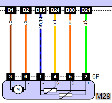
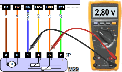
Throttle Actuator Potentiometers:
On this page, the potentiometer of the throttle valve actuator has been used as an example before. The following diagram shows the servomotor (left) and the two potentiometers with common supply and ground and two signal connections (right). The signal connections (pins 4 and 5 in the plug of the potentiometer) give signals with a difference in voltage profile:
- the course is linear at a different stress level, with the stresses rising and falling simultaneously, or;
- the signal voltages are opposite to each other.
The three images below show three measurements of the throttle position sensors and their combined power supply and ground. The supply voltage is again 5 volts and the signal voltages are within tolerances.
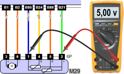
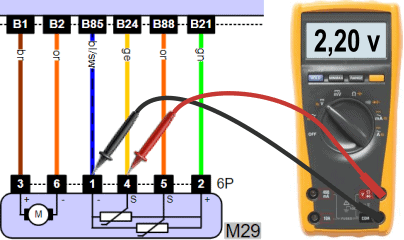
In the event of a malfunction, the level of the signal voltage may deviate. Two situations are possible:
- One of the signal wires has a fault. Because the ECU compares the two signal voltages, it recognizes this erroneous signal and goes into emergency mode. This is accompanied by an illuminated engine management light and reduced engine power;
- The supply or ground wire contains a contact resistance: in this case there is a voltage drop across the relevant wire, causing beide potentiometers give too low a signal. Because the signal voltages are compared to each other and they are relative to each other did not deviate, this is determined by the ECU did not recognized. The signal voltages that are too low are accepted by the ECU and result in incorrect throttle control. The ECU continues to control the throttle valve actuator until the desired position is reached. This can lead to subsequent malfunctions in sensors and actuators related to the air supply due to a mixture that is too lean (positive fuel trim), malfunctions in the lambda circuit, malfunctions with regard to the MAP sensor or the EGR.

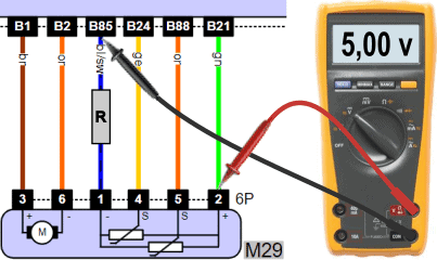
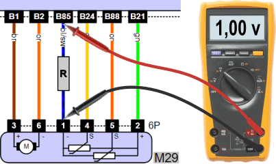
The fault in the above situation can be rectified by replacing the ground wire between pin B85 of the plug on the ECU and pin 1 of the plug on the throttle valve.