Subjects:
- Opamp introduction
- Inventive Amplifier
- Non-inventive amplifier
- Difference / Differential Amplifier
- Inventive adder
Opamp introduction:
Opamp stands for operational amplifier; in Dutch that means: operationele versterker. Op amps are used in integrated circuits (such as on printed circuit boards in computers) with a very high gain factor, which amplifies the input voltage (eg from a sensor). The amplified signal is then suitable as an input signal for a control device, such as the ECU. The amplification factor can be as much as 100.000 and more.
By means of resistors, the amplification factor can be reduced, so that the output voltage can never exceed the (previous) maximum value.
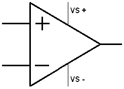
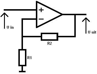
The picture shows the symbol of an opamp. The VS + and VS – connections are often omitted.
When there is a voltage difference across the opamp and the voltage on the + is greater than on the -, the output voltage is amplified. Conversely, when the – is greater than the +, the output voltage is negatively boosted. This can be consciously used with an inventing amplifier. With an inventing amplifier, the output voltage will be negative. The plus and minus signs in the opamp picture will also alternate. As the opamp is now pictured, it is a non-inventive amplifier. The output voltage will be positive.
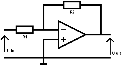
Inventing op amp:
The positive input of the opamp is grounded. The positive voltage is therefore always 0. The resistance values determine the amplification factor (A). The voltage “U in” can be a sensor signal that is amplified to the ECU which is connected to the output U out.
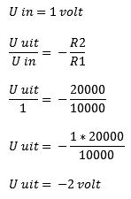
With an inventing opamp, the amplification factor can be calculated with the following formula:
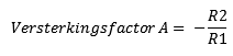
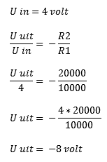
A calculation example follows with U in = 1 Volt and U in = 4 Volt. By multiplying the fractions crosswise, the stress U in is multiplied by the amplification factor. Calculates the output voltage (U out).
When the gain is increased (for example to 100) you will see that with a minimal increase of U in, the U out rises very fast. Never forget that the output voltage of the inventing opamp is negative.
R1 = 10kΩ = 10000Ω
R2 = 20kΩ = 20000Ω
Non-inventing opamp:
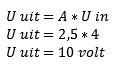
Compare the non-inventing op amp with the inventing op amp. The difference is, as the name suggests, this opamp does not invent (reverse) the voltage. So the outgoing voltage is positive. We perform the following calculation in the simple way, by multiplying the amplification factor A by the input voltage.
R1 = 10kΩ = 10000Ω
R2 = 20kΩ = 20000Ω
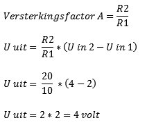
Difference / Differential Amplifier:
The differential/differential amplifier compares the 2 input signals (U in 1 and U in 2) and then amplifies that. The figure below compares the voltages U in 1 and U in 2. These are 2 and 4 Volts. The difference between these is 2 Volts. This is amplified by the amplification factor, which depends on the resistance values R1 and R2:
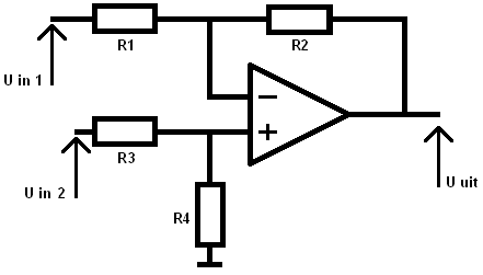
U in 1 = 2 Volts
U in 2 = 4 Volts
R1 = 10 kΩ
R2 = 20 kΩ
R3 = 10 kΩ
R4 = 20 kΩ
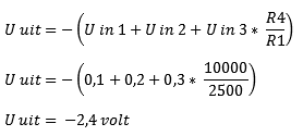
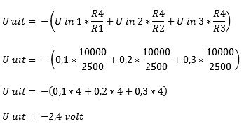
Inventive adder:
Calculating the inventing adder can be done in 2 ways. The easiest way is if the resistors R1, R2 and R3 all have the same resistance values as in the example, (way 2). If these resistors are unequal (if eg R1 has a different value than R2 and R3) then way 1 should be used :
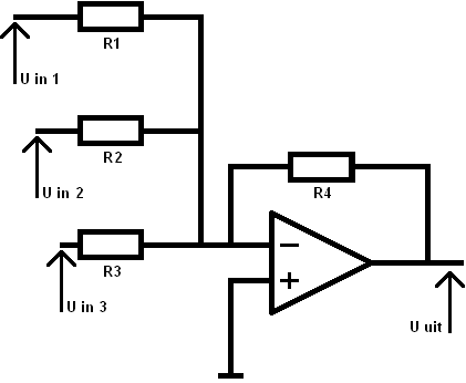
U in 1 = 0,1 Volts
U in 2 = 0,2 Volts
U in 3 = 0,3 Volts
R1 = 2,5 kΩ
R2 = 2,5 kΩ
R3 = 2,5 kΩ
R4 = 10 kΩ
Way 1 (R1, R2, and R3 are not equal)
Way 2 (R1, R2 and R3 are equal to each other)