Subjects:
- General
- Overhead camshaft
- Underlying camshaft
- Fast camshafts
- valve overlap
- Variable valve timing and valve lift
- Lubrication
General:
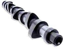
The camshaft is an important part of the engine. The camshaft ensures that the valves open and close allowing air to flow in and out of the cylinder. The camshaft rotates so that the cam opens the valve against the spring force of the valve spring. The valve spring ensures that the open valve is closed when the cam continues to rotate.
The camshaft is located at the top or bottom of the cylinder head, or at the bottom of the engine block. The camshaft is driven by the timing belt, chain or sprockets. See more about this in the chapter distribution.
Overhead camshaft:
The overhead camshaft is now only used. The camshaft is then placed in the cylinder head. The advantage of engines with an overhead camshaft is that they can handle higher speeds than engines with a lower camshaft.
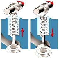
The left image shows that the valve is closed because the valve spring compresses the valve and that the camshaft rotates clockwise. In the right image, the camshaft is twisted, causing the cam to push the valve down. The spring is now compressed, pushing the valve down. The moment the camshaft has turned further, the valve spring will push the valve back up. The valve spring exerts a counter pressure of approximately 20 kg.
The valves of a four-stroke engine are opened by 1 or 2 camshafts. In the version with 1 camshaft, it operates both the intake and exhaust valves.
On the 2 camshaft version, one camshaft operates the intake valve(s), and the other operates the exhaust valve(s). The 2 camshafts can be driven one after the other by the 1 timing belt, but there are also systems that one camshaft drives the other by means of a separate belt or chain (see the images below)
The images below are just examples of the timing belt construction. The principle is the same with a timing chain.
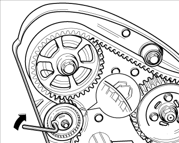
The top left image is of an engine fitted with a single camshaft. This operates both the intake and exhaust valves. This is usually applied to, for example, four-cylinder engines with 8 or 12 valves (ie with 2 or 3 valves per cylinder).
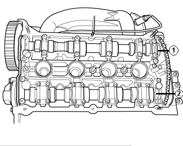
The middle image is of a twin cam engine driven by two timing belts. The camshaft gear (1) is directly driven by the crankshaft with the large belt. At the back of the pulley of gear 1 is a small gear, over which the rear belt runs. This rear (small) belt drives the camshaft gear (2). The small belt needs a separate tensioner. Usually this is applied to four-cylinder engines with 16 or more valves. (so 4 or more valves per cylinder)
The picture on the right is of a motorcycle engine with two camshafts. The camshafts are driven by both a belt and a chain. Camshaft 1 is driven by the timing belt, which is driven by the crankshaft. Camshaft 2 is driven by means of the chain which is driven by camshaft 1. This chain is mounted under the valve cover with a tensioner or an adjusting mechanism. This is usually used in, for example, four-cylinder engines with 16 or more valves. (four or more valves per cylinder)
Underlying camshaft:
In the past, engines were equipped with an underlying camshaft. Nowadays, passenger car engines are only equipped with an overhead camshaft. The construction with the underlying camshaft is disappearing. The disadvantage of this construction is that these engines can handle less high speeds, because there is a lot of mass between the camshaft and the valve. At high speeds, there will be too much play and the valve will no longer open and close at the correct times.
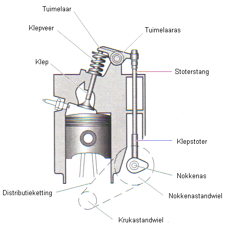
The crankshaft drives by means of a small timing chain or belt to the underlying camshaft (see image below). The camshaft pushes the valve tappet and pushrod straight up. The right side of the rocker arm is pushed up. The rocker arm 'tumbles' around the rocker arm axle, pushing the left side down. This forces the valve downwards against the force of the valve spring. When the camshaft is rotated further, the valve spring presses the valve closed and the rocker arm returns to its starting position.
Fast camshafts:
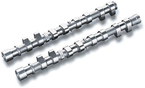
When the cam is more oval and longer, the valve will stay open longer. This allows more air to flow into the cylinder. This results in capital gains. This principle is used, for example, in engine tuning. This is then called 'fast camshafts'. When the end is sharper (more in a point shape) the valve will close faster again. It should also be slightly convex, otherwise the valve will bounce back on the seat at too high a speed, causing hard wear on the valve seats. When designing an engine, this is also carefully tested to ensure that camshafts are placed that are most optimal for power, fuel consumption and emissions.
Valve overlap:
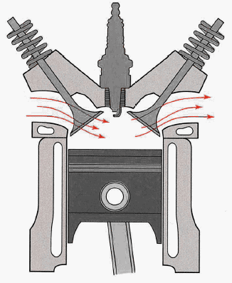
During valve overlap, the intake and exhaust valves are briefly open at the same time. At the end of the exhaust stroke, when the piston is near TDC, the intake valve opens before the exhaust valve is closed. In this situation, the velocity of the exhaust gases leaving the combustion chamber is so high that intake air is already drawn in by the vacuum effect. After the exhaust valve is closed and the piston moves to the ODP, the intake valve opens all the way. The inlet air will thus fill the combustion chamber.
The advantage of valve overlap is that the speed of the inflowing air is increased when the inlet valve is opened, resulting in a higher degree of filling.
The illustration shows the situation where the inlet valve (left) and exhaust valve (right) are open at the same time.
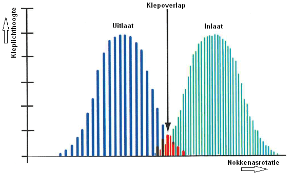
The diagram shows the opening and closing of the exhaust and inlet valves. As the camshaft rotates, the exhaust valve opens and closes again (the blue lines). The valve overlap occurs in the center of the graph. This is shown in red. The inlet valve (shown with green lines) is already slightly open here.
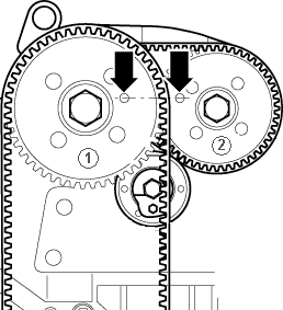
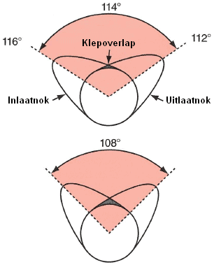
The valve overlap is obtained by the cam shape. The image below shows that at the top camshaft, the highest cams are 114 degrees apart. In the center of the image, the valve overlap occurs because the end of the intake cam and the beginning of the exhaust cam are higher than the rounded portion of the camshaft. This is the part where the intake and exhaust valves are open at the same time.
The closer the lugs are placed together, the more overlap occurs. This can be seen in the difference between the upper and lower camshafts, where the cams in the lower camshaft are 108 degrees apart.
Valve overlap therefore always takes place and cannot be changed by the fixed cam shape on the camshaft. The amount of valve overlap that takes place is determined by the engine manufacturer.
Variable valve timing and valve lift:
The power of the engine is largely dependent on the camshaft. If it has cams that are long and oval, the valves will stay open longer. So more air can get in and out of the engine, which produces more power. If the cams are shorter and more pointed, the valve will open less wide and close sooner, allowing less air to go in and out, so it will also deliver less power. The advantage is that the fuel consumption can be reduced as a result.
Low-load motor revs require:
- Intake valves open late and close early.
- Exhaust valves open late and close early.
High engine revs with high loads require:
- Open intake valves early and close late.
- Open exhaust valves early and close late.
Car manufacturers always look for a middle ground. Variable valve timing adjusts the camshaft to the required position at the rpm the engine is running at. Variable valve lift is also a technique to obtain various advantages by changing the distance at which the valve opens.
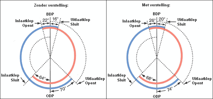
At variable valve timing turns the camshaft relative to the adjustable camshaft sprocket (see picture). With this system it can be controlled that the valves open earlier or later, but it cannot be controlled that the valves remain open longer. If the valve opens earlier, it will also close sooner, as the camshaft shape remains the same. On the page variable valve timing more explanation is given here.
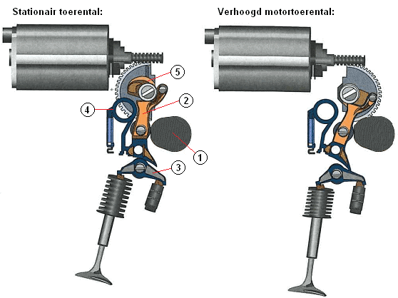
Variable valve lift is a technique that ensures that the height of the valve is adjustable. This controls how far the valve opens. This is beneficial for both fuel consumption and engine power. The image below is an example of this. This is BMW's Valvetronic.
Variable valve lift is only applied to the intake camshaft. There are several techniques that are used by different manufacturers. At page variable valve lift the different techniques are described in detail.
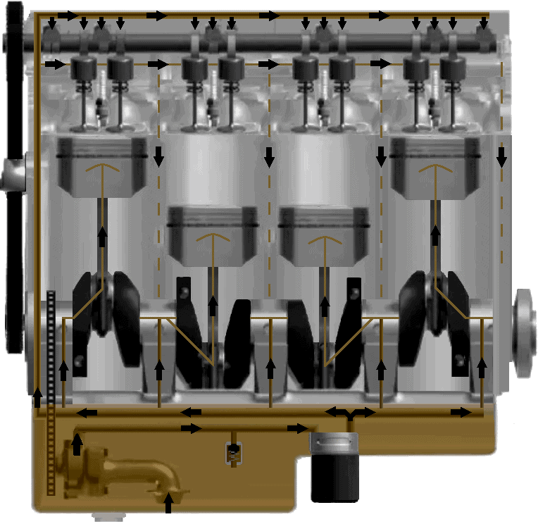
Lubrication:
The camshaft must be lubricated, as well as all other moving components in the engine. The camshaft is supplied with oil in the right places via pipes with holes or nozzles. The operation of the entire lubrication system is described on the page lubrication system.