Subjects:
- MOS transistor general
- MOS transistor as switch
- MOS transistor characteristic
MOS transistor general:
The MOSFET (this is the abbreviation of Metal Oxide Semiconductor Field Effect Transistor) is used in many microcontrollers. The MOSFET can best be compared to a regular transistor, because both the FET and the transistor have three terminals and are therefore able to send currents. The difference between the FET and the common transistor is that the FET only needs a voltage to switch while the transistor needs current. The FET is therefore controlled without energy, which benefits the minimal heat development in a microcontroller.
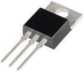
The picture shows a MOSFET. The three legs are the "gate", "drain" and "source" connections.
MOS transistor as switch:
At the N-MOS transistor, the gate must go positive to turn on the FET. The P-MOS transistor is not yet described on this page at this point.
The left connector becomes the gate (g) called the top one is the drain (d) and the bottom one becomes the source(s) .
If a positive voltage is applied to the gate, a large concentration of electrons is created under the influence of the electric field directly below the gate insulation. An n-channel is thus created between the drain and source, which enables direct conduction between the drain and the source. The arrow in the symbol indicates the electron flow direction. With the n-MOS, the arrow points to the channel.
The gate is also called the gate electrode. Compared to the ordinary transistor, the drain corresponds most closely to the collector and the source to the emitter. Normally no conduction is possible between the drain and the source, because there is an np-pn transition between them. This is comparable to two diodes with the cathode against each other.
The schematic shows a battery, switch, LED and MOSFET. When the switch is closed, a voltage is applied to the gate. This creates a conduction between the drain and source, causing a current to flow. Because a current will flow through the resistor and the LED, the LED will light up.
In this example, the gate is controlled by the manual switch. In reality, the gate is controlled by an ECU. The drain is connected to the negative connection of an actuator; in the schematic the LED is the actuator. The source is connected to the ground of the battery.
MOS transistor characteristic:
Just like the common transistor, the MOSFET also has a characteristic. The characteristic can be used to determine what the voltage on the gate must be to drive the actuator with the MOSFET.
In the image below on the left is a schematic diagram with a 5 Watt lamp, which is controlled by the MOSFET. The characteristic of the MOSFET is shown on the right. The current intensity through the drain can be seen on the vertical axis (the Y-axis) of the characteristic curve. The voltage difference between the drain and the source can be read on the horizontal axis (the X-axis).
If the transistor conducts because the ECU supplies the gate with a power supply, a current will flow and the lamp will light up. The voltage measured with the voltmeter in this situation is 12 volts. With the 5 Watt lamp, a current of 0,42 Ampere (420 mA) flows through the drain.
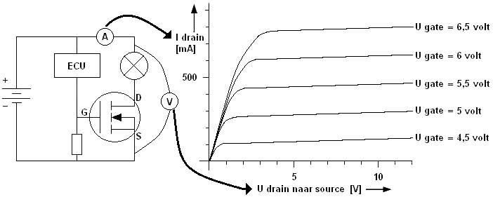
Now that the voltage of 12 volts and the current of 420 mA are known, these two intersections in the characteristic can be filled in. A line can be drawn between these two points. This is the tax line. Using this load line, it can be determined what the minimum voltage on the gate must be in order for the MOSFET to conduct. To ensure that the MOSFET is completely turned on, the voltage on the gate is always taken greater than necessary. Think of the factor 1,5 Ibk for the normal transistor.
In the characteristic it can be read that the ideal voltage on the gate is 5,5 volts. The higher the current through the drain, the higher the gate voltage must be for the MOSFET to conduct.
Related page: