General: Measuring tools are often used in automotive technology, for example during an engine inspection. Measuring tools are also used to measure the thickness of the brake linings or the brake disc. In order to be able to perform a measurement, it is important to know the measuring accuracy with which the tool has been carried out. The inner measuring jaws of a caliper can measure the cylinder diameter, but it is not accurate enough (1/20 mm). A dial indicator is much more accurate (1/100 mm).
The most common workshop measuring tools and their accuracy are:
Vernier Caliper (0,05mm, which is the same as 1/20mm.)
Micrometer (0,01 mm, or 1/100 mm.)
Dial indicator (0,01 mm.)
Feeler gauge (0,05 mm.)
Plastigage (accuracy depending on the version).
On this page an explanation is given about setting, reading and possibly calibrating the aforementioned measuring tools and examples of measurements are given.
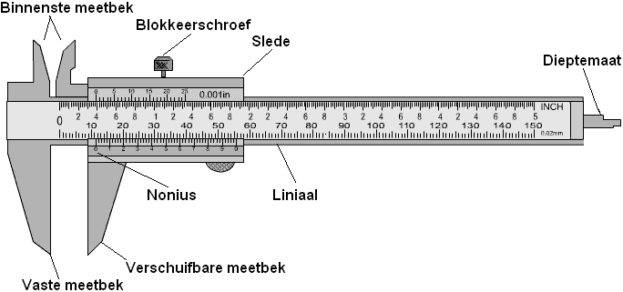
Vernier Caliper: The caliper is a widely used measuring tool in automotive technology. With the vernier caliper, the inside, outside and depth dimensions of a component can be measured accurately to the twentieth millimetre.
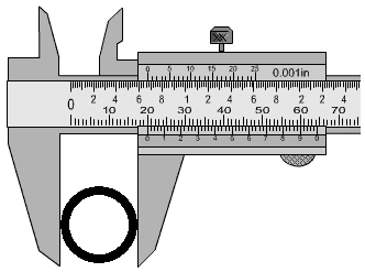
Measuring with the fixed jaw: The size can be read by clamping the component in the fixed measuring jaw. 20mm can now be read on the ruler. This is the outer diameter of the ring.
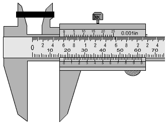
Measuring with the inner measuring jaw: The inner diameter can be read by clamping the measuring jaw in the inside of the ring. This is 18mm. That means that the ring (20-18) = 2mm thick.
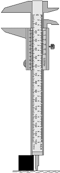
Measuring with the depth gauge: For example, for objects that cannot be detached from the ground or cylinders with a bottom, the height can be measured using the depth gauge. By placing the end of the depth gauge on the substrate and the thick part of the caliper on the component, its height can be determined. In this case, the height of the black block is determined:
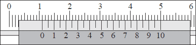
To read the vernier caliper, one should also look at the tenths of millimeters. The place where the next line of the vernier is exactly equal to the line of the ruler indicates the measure in tenths of millimeters (the number after the decimal point). In the picture, the 0 of the vernier is 1,1 cm, so 11 mm from the ruler. The line of the number 10 on the vernier is also equal to the line on the ruler. This means that there are exactly 11,0 mm is measured.
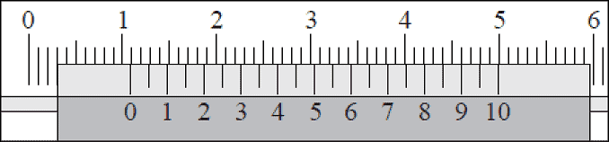
In the next measurement, the vernier has shifted a little bit to the left and we are dealing with a number after the decimal point. We look at the place where the next line of the vernier is exactly equal to the line of the ruler. In the image, the 0 of the vernier is 1,1 cm, so 11 (whole) millimeters. The line of the number 9 on the vernier is also equal to the line on the ruler. That means that exactly 10,9 mm is measured.
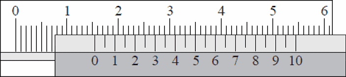
The measurement in the picture follows the same principle. In this case, the 0 of the vernier is halfway between the 15 and 16 mm of the ruler. Then in principle you already know that the decimal number should be around 4, 5 or 6. The lines of the ruler and vernier match at 5; So now (15+0,5) = 15,5 mm is measured.
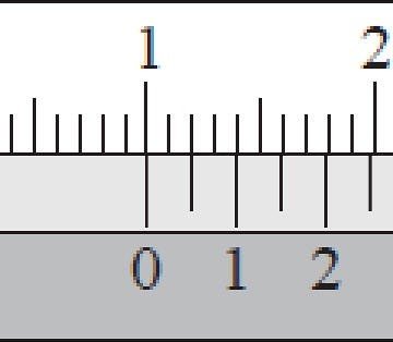
There are also small dashes between the numbers on the vernier. These indicate the five hundredths of a millimeter. The line between the 0 and the 1 on the vernier matches the line on the ruler. In the picture, (10 + 0,05) = 10,05 mm is measured. Reading a five-hundredth requires a trained eye.
In this animation the reading of the vernier with red arrows is clarified.
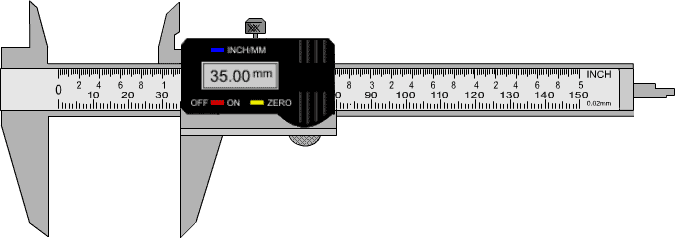
A vernier caliper can also be digital, as can be seen in the image. The dimensions of the component being measured can be read in the digital display. This can often also be set to both inches and millimeters.
There are also calipers with an analog dial indicator where the digital display is in the image above. This caliper is not widely used, but it is just what the user prefers to use.
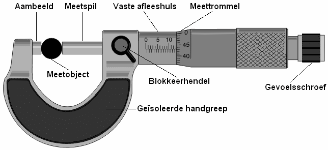
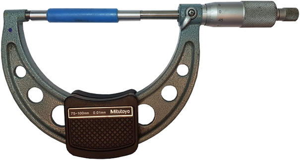
screw size: The micrometer (also called micrometer or stirrup micrometer) can Wordenused to measure components up to 25 mm in size with an accuracy of one-hundredth of a millimeter (0,01 mm). With one revolution of the measuring drum, the measuring spindle is moved 0,5 mm.
The micrometer must always be held by the insulated handle, as the heat from the hands affects the measurement result. Local heating in the micrometer can cause the material to expand slightly. Certainly for a measurement where the result must be measured to the nearest hundredth, it is important to adhere to the regulations. The component to be measured should be placed between the anvil and the measuring spindle. By rotating the measuring drum, the measuring spindle moves back and forth. Before the measuring spindle touches the component, the last distance must be tightened with the feeler screw. The feel screw contains a click mechanism that produces a 'clicking' sound when a certain force is applied. At that moment you know that you are not allowed to turn the meter any further. If you tighten the micrometer too much, you can get incorrect measurement results. The measuring drum can be locked against further turning with the locking lever.
Below is an image of a micrometer where the size of a ball bearing (the measuring object) is measured.
In the picture above, the ball bearing has a thickness of 13,43 mm. On the top scale you see 10, with 3 bars next to it. Each bar is a millimeter, so 10+3=13 mm. The number after the decimal point is read on the measuring drum. Here are the numbers 40 and 45. If you look closely you can see that the line of the scale is equal to 43. Together this makes 13,43 mm.
The measuring drum has a scale from 0,0 to 0,49 mm. This is because the scale with the whole millimeters (to the left of the measuring drum) also contains half millimeters; the lower bars indicate the half millimeters. Below are some examples.
Whole millimeters are displayed on the horizontal line. In this case it is 13mm. The 16mm mark on the measuring drum is equal to the horizontal line on the reading sleeve. The size indicated with this image is (13 + 0,16) = 13,16 mm.
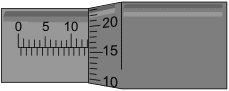
In the picture, the line below the line of the scale of the reading sleeve is visible. This dash below the horizontal line indicates that it is half a millimeter. According to the scale, it is therefore at least 5,5 millimeters (without including the measuring drum). The scale on the measuring drum indicates 36. The size that is now indicated is in total (5,5 + 0,36) = 5,86 mm.
In this image, the line at the bottom of the scale is again closest to the measuring drum. So it is in any case again 12,5 mm according to the horizontal scale. Then we add the indicated value of the measuring drum; this value is 0,35 mm. Then we add 12,5 and 0,35 together. This is together (12,5 + 0,35) = 12,85 mm.
In this image, the indicated size is (16 + 0,355) = 16,355 mm.
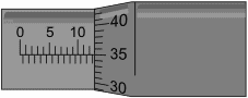
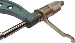
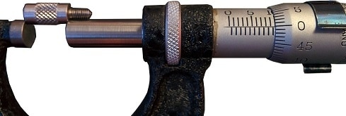
The picture shows the micrometer value of 75,235 mm. The scale on the measuring drum is between 23 and 24 mm. Because the caliber is 75 mm, the micrometer deviates by 0,235 mm. Any measurement that will be performed will therefore be too high. With an adjustment fork intended for this purpose, the reading sleeve should be turned in relation to the handle. The adjustment fork can be seen in the picture above.
Before measuring with the micrometer, it must first be calibrated. Incorrect calibration leads to measurement errors! The calibration of the micrometer is carried out with the aid of a gauge intended for this purpose. The caliber in the picture below is exactly 75,00 mm. That means when the micrometer measures the caliber, the micrometer must indicate this number exactly. In case of an incorrect measurement value, we must first calibrate the micrometer by turning the inner drum with the fork.
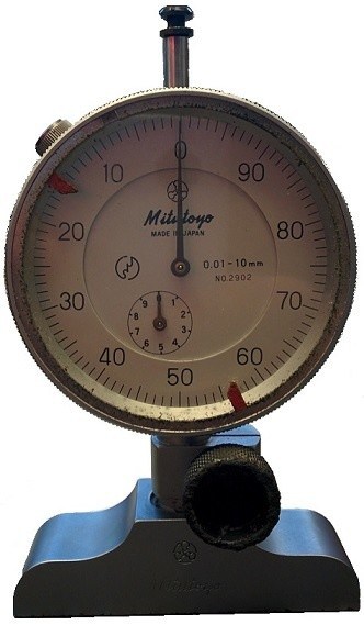
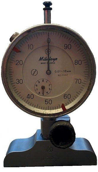
Dial indicator: A very accurate depth measurement can be performed with the dial indicator. The small hand on the inside indicates the whole millimeters and the large hand indicates the number after the decimal point. When the dial indicator is on a level surface, it should read 0,00mm as shown in the figure below. The outer ring can be turned to allow calibration. If 0,3 mm is measured when it is standing on a straight surface, then the outer ring must be turned so that the large hand indicates 0.
The dial indicator in the picture indicates 5,00mm. The small hand is at the 5 and the large hand at the 0. If the large hand were at 81 and the small hand between 5 and 6, the meter would indicate a value of 5,81 mm. The further the measuring pin is pushed upwards on the underside, the smaller the reading will be.
The dial in the micrometer reads: 0.01 – 10 mm. This means that the micrometer can indicate a value between 0.01 and 10 mm. It is therefore not possible to carry out a depth measurement with a depth of 12 mm, because the measuring pin is too short for that and the hands cannot indicate that. In order to be able to measure values larger than 10 mm, various extensions are supplied with the micrometer. An example of this can be seen in the image. The extension is measured here with a micrometer. This indicates a value of 10,0mm.
Only the barrel-shaped part is measured here, not the screw thread. By mounting this extension on the micrometer, the measuring pin is no longer too short. The value of, for example, 12 mm can now still be measured. It should now be noted that the size of the extension is added to the measured value. Here is an example: the moment the micrometer indicates a value of 5,19 mm, the actual size is therefore the measured value + the length of the measuring tip, so 5,19 + 10,00 = 15,19 mm.
Measurements are made with the dial indicator on these pages:
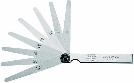
Feeler gauge: The feeler gauge is used to measure the gap between two parts. The feeler gauge consists of a number of metal strips, each of which has a different thickness. The thickness is stated on the metal strip. The bottom strip of the feeler gauge in the illustration below reads “30”. This means that the metal strip is 0,30 mm thick.
To measure the space between two parts, any metal strip has to be unfolded and slid between the parts. If the strip can be moved in between very easily or even without resistance, then the space is greater than the thickness of the strip. A thicker metal strip must therefore be unfolded. If the strip no longer fits in between, this strip is too thick. If the strip can be slid between the parts with some resistance, then that is the right size.
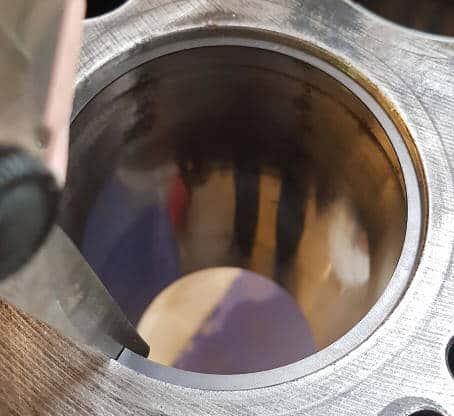
The following figure measures the lock clearance of a piston ring.
These pages take measurements with the feeler gauge:
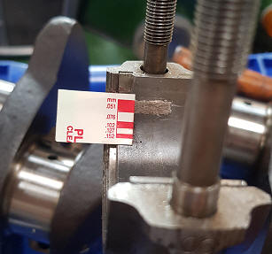
plastigage: Plastigage can be used to check the clearance between plain bearings. Plastigage is a special plastic wire that must be applied to the part between which the clearance is to be measured. The bearing cap must then be secured, so that the plastigage is pressed flat. The deformation of the plastigage is a measure of the clearance.
There are different colors of plastigage. Each color represents a different size.
Green: for a bearing clearance of 0,025 to 0,076 mm.
Red: 0,050 – 0,150mm.
Blue: 0,102 – 0,229mm.
Yellow: 0,23 – 0,51mm.
A measurement with plastigage is performed on this page: