Subjects:
- Measuring Piston Diameter
- Measuring cylinder diameter
- Piston Clearance
Measuring piston diameter:
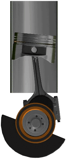
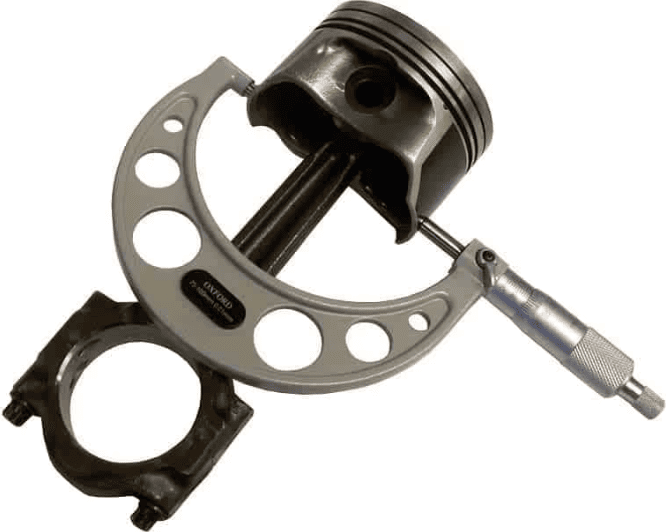
With a micrometer we can determine the diameter of a piston. We apply the micrometer perpendicular to the piston pin; this is where most of the forces occur as a result of the guideway force. When the piston wears, the diameter will decrease the most here.
The piston size is stated in the manufacturer's technical data.
Measuring cylinder diameter:
The cylinder diameter may be subject to wear and tear, partly as a result of the guideway force, get bigger. With the cylinder measurement we can determine whether there is wear and to what extent any wear falls within the tolerances.
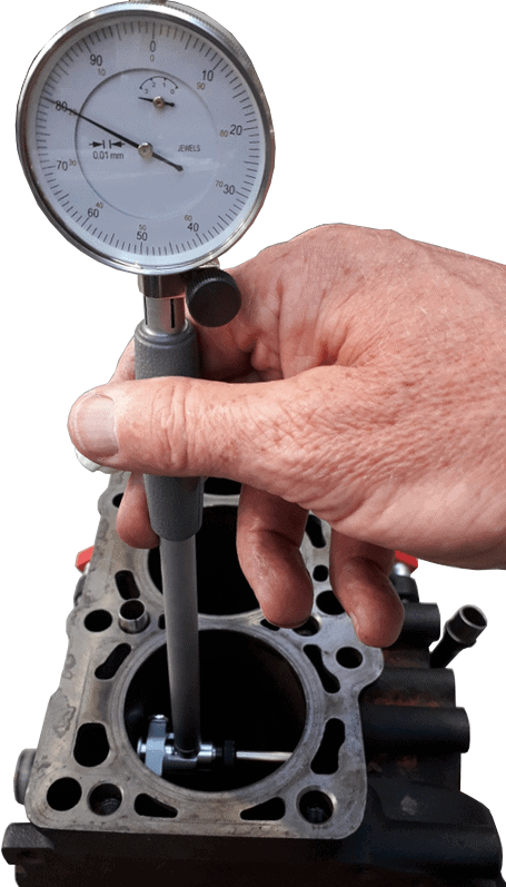
We perform a cylinder measurement with a dial indicator that is attached to a bore gauge.
With a cylinder gauge we can measure the difference in diameter at various places in the cylinder space. This gives us a wear pattern of the cylinder in question. The diameter can be measured to within 0,01 mm.
The cylinder gauge consists of a dial indicator, a connecting rod with a probe at the bottom and an interchangeable rod. Depending on the cylinder diameter (bore), this rod must be selected with the correct length. There are usually around ten different sizes in the suitcase. If the desired size is exactly between two measuring calibers, a shim can be fitted to the smallest caliber to get the desired length.
Example:
The cylinder diameter is 87,00 mm. We choose the rod with a length of 85,00 mm and fit a 3 mm shim to get a length of 88,00 mm. The length is now 1 mm more than the cylinder diameter: this is important for this measurement, because the cylinder diameter has increased in case of wear. We determine the length of the rod with a micrometer.
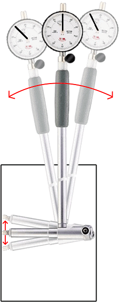
To start the measurement, we insert the lower part of the cylinder gauge into the cylinder space. The following text is about the measurement in the picture:
- The right part has a - not adjustable in length - wheel;
- The left part is the adjustable measuring pin to which we mounted a rod of the correct length when setting it up;
To determine the smallest diameter, move the cylinder gauge must be moved back and forth. The pointer in the micrometer moves from left to right. The image shows three positions: left, center and right. The middle position is shown as dark gray, the other positions are light colored.
- Move to the left position: Measuring pin springs out of the cylinder gauge. The pointer indicates 0,1mm of movement;
- Move to the right position: most pin springs out of the cylinder gauge again, and the pointer also indicates 0,1 mm again.
- Dial indicator in the middle: the diameter of the cylinder is smallest here. The measuring pin is therefore pressed in to the maximum. The pointer now indicates 0 mm.
The pointer does not necessarily indicate 0 mm when the cylinder gauge is in the middle. Taking into account that the zero point is located at 50 on the dial (the pointer has been rotated 180 degrees from the current situation), the 0,1 mm deflection will cause a movement between 50 and 60 on the dial; again 0,1 mm.
The above steps should be repeated in a number of places. When the dial indicator in the center reaches 0 mm in all places, there is no wear. However, if the pointer moves past 0, the space has become larger. The stroke of the pointer has then become larger: for example a total of 1,1 mm instead of 1,0 mm. This means that there is a wear of 0,1 mm.
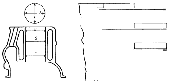
The following figure shows a cylinder chamber with three possible measuring heights: 1, 2 and 3. The measurement should be carried out in both the longitudinal and transverse directions.
The diameter at the top of the cylinder (3) will be the largest: the forces of the piston against the cylinder wall are minimal here. The force is greatest halfway through the cylinder: with wear, this diameter will be greatest.
A tip is to make a sketch for such a measurement and write down the measured values on it. If the diameter is greater than the value specified by the manufacturer, the relevant cylinder is rejected.
Piston Clearance:
The clearance between the piston and cylinder depends on both the piston diameter and the cylinder diameter:
- piston wear: diameter decreases;
- cylinder wear: diameter increases.
Wear is a result of, among other things, the guideway force which occurs when the piston is pushed down by the combustion pressure and the crank-connecting rod mechanism. More wear results in a greater distance between the piston and cylinder. The result is that the piston has more freedom of movement and will “tilt”. This gives ticking noises, causes higher oil consumption (the lubricating oil can now easily pass the piston into the combustion chamber) and can only be remedied by a major repair.
A certain piston clearance must always be present in order to:
- allow expansion of parts when heated;
- space for a lubricating oil film.
The maximum clearance between piston and cylinder is stated in the factory data. Therefore, always read the values specified by the manufacturer. In general,: 0,01 mm per cm of piston diameter is used for the average piston clearance. With turbo engines, this is slightly wider, namely 0,015 mm per cm of diameter. In this case, if we have a piston with a diameter of 80,00 mm, the bore of the cylinder should be (80,00 + (8 * 0,01 mm) = 80,08 mm.
If the piston clearance is too large, you should check the factory specifications for possible follow-up steps:
- Drilling and honing cylinders, as well as mounting oversized pistons due to the larger cylinder diameter, is not allowed by all manufacturers. It is also necessary to check whether such an adjustment has already been made in the past. Some manufacturers prescribe that a maximum of 3x an excess may be mounted;
- If the mounting of oversized pistons is not allowed, or if the costs are too high, it is better to choose to replace the rotating part.