Subjects:
- Measuring Radial Crankshaft Play
- Measuring crankshaft axial play
To measure radial crankshaft clearance:
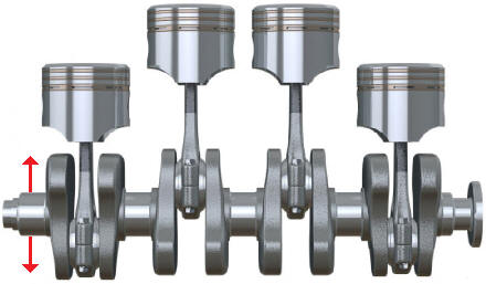
The radial play is the play of the crankshaft between the main bearings. There should always be a small clearance because an oil film has to be formed. The oil film fills the space between the two moving parts. The figure below shows in which direction the radial play is.
The radial clearance must of course not be too small or too large. If the play is too small, friction can arise between the crankshaft and the plain bearings. If the clearance is too large, there is too much space between the crankshaft and the plain bearings. The consequences of incorrect play can include accelerated wear of the plain bearings. This will cause noise in the engine.
The clearance on the crankshaft journal bearings and connecting rods can be measured with plastigage. Plastigage is a special plastic wire.
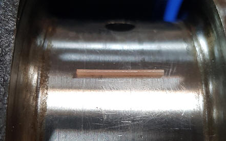
A little plastigage should be placed on a clean surface. This could be a crankshaft bearing. Then the bearing cap must be mounted with the correct tightening torque. The plastigage now located between the crankshaft bearing and the bearing cap will deform.
After the bearing cap bolts are tightened, they can be disassembled again. The imprint of the flattened plastigage will now be on the bearing and bearing cap (see images below).
Since the radial crankshaft clearance is different for each engine, plastigage comes in three different sizes;
- Green: for a bearing clearance of 0,025 to 0,076 mm.
- Red: 0,050 – 0,150mm.
- Blue: 0,102 – 0,229mm.
- Yellow: 0,23 – 0,51mm.
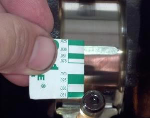
The width of the squashed plastigage indicates the clearance that exists between the crankshaft and the bearing cap. The thicker the line, the more the bearing cap is pushed against the crankshaft, so the smaller the clearance. When the plastigage is almost not deformed, the clearance will be very large.
On the packaging of the plastigage is a reference width with a measurement in millimeters or inches. By holding the card next to the flattened plastigage, you can determine how many millimeters the clearance is.
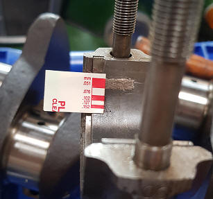
In the green card image above, the clearance is 0,038mm. This clearance should be compared with the factory data. Tolerances are often specified herein. These amount to 0,030 – 0,050 mm for the motor in this measurement. The measured value is within tolerances, so the clearance is OK. The same applies to the measurement with the red card, where the clearance is 0,51 mm. If the clearance would be too great, thicker plain bearings could be chosen.
Measuring crankshaft axial play:
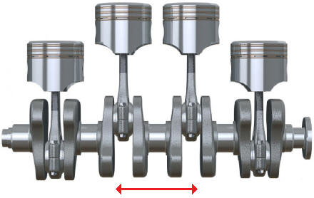
The crankshaft axial play is the play that is present in the longitudinal direction of the crankshaft. When the clutch is actuated, force is applied in the longitudinal direction of the crankshaft. This is the axial direction. To absorb these axial forces, axial bearings are mounted on the crankshaft. In the figure, the axial direction is indicated by arrows.
Measuring the crankshaft axial play can be done with a dial indicator. See the page Mechanical Measuring Tool for more basic information about the dial indicator.
Step 1.
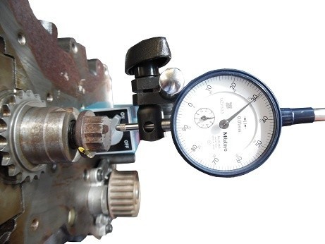
Mount the dial indicator on a fixed point on the engine block. In the picture, the dial indicator is mounted on the engine block. The pin is not touching the crankshaft bolt yet.
Step 2.
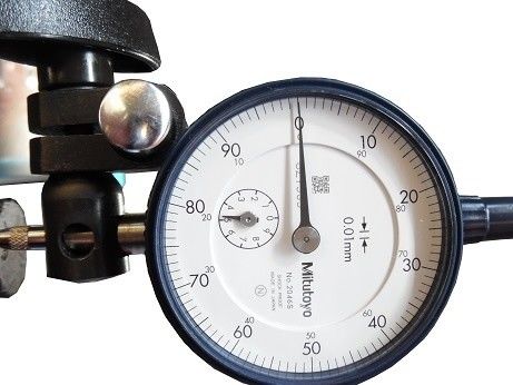
Set the dial gauge with a bias greater than 2 millimeters. This means that the measuring pin of the dial indicator is pressed in at least 2 mm while the crankshaft is not yet moved. If no preload is set, there is a chance that the measuring pin will no longer touch the bolt during the crankshaft movement. In the picture, the preload is set to 5 mm (the small hand indicates the whole millimeter).
Push the crankshaft (lengthwise) to one side as best you can. Then turn the outer ring over so that the zero on the dial is behind the pointer.
Step 3.
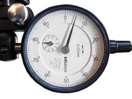
In the previous step, the pointer was exactly at 0 with a preload of 5mm while the crankshaft was moved to one side. With every movement now made, the needle will indicate more or less millimeters. The crankshaft should now be pushed in the other direction in the axial direction. The pointer will indicate a different value from 0.
The figure shows a clearance of 0,05 mm.
Refer to the manufacturer's data for the respective motor to compare the measured value with.