Subjects:
- Valve guide clearance
- Replace valve guides
To measure valve guide clearance:
Worn valve guides can cause the following complaints and defects:
- burnt valve discs;
- broken valve;
- rocker arm wear;
- increased oil consumption.
With a disassembled cylinder head, we want to measure the clearance between the valve stem and the valve guides for the above complaints. Not all manufacturers describe the maximum allowable clearance in the service documents. In that case we can use the guideline values in the table below:

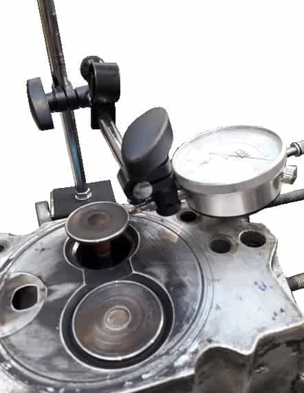
The following figure shows the measurement where the valve guide clearance of the exhaust valve is measured. The dial indicator is placed on a tripod and thus has a fixed position. We place the needle of the dial indicator with a pretension of at least 2 mm against the valve disc of the valve, which has been slid approximately 10 mm out of the cylinder head.
With moderate force we try to move the valve back and forth in the direction of the dial indicator. The dial indicator hand will move back and forth over a certain area of the dial as it moves. The stroke the pointer makes indicates the play.
Replace valve guides:
If we measure too much clearance between the valve guide and the valve stem, we consult the technical data of the engine in question to determine whether the valve guides can and may be replaced. If this is not possible according to the factory instructions, a reputable overhaul company often knows how to do this. Otherwise it would mean that the entire cylinder head would have to be replaced.
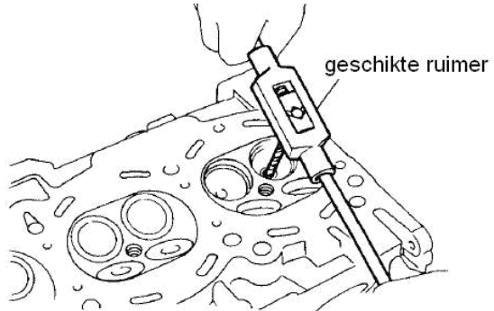
If it is possible to replace the valve guides, equipment must be used to remove the valve guides, ream the hole and install new valve guides. In most cases the cylinder head must be heated to well above 100 degrees Celsius and the valve guides must be pressed into the holes.
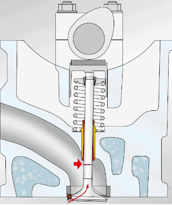
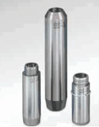
The two images below show the position of the valve guide in the cylinder head (left) and three different valve guides (right).