Subjects:
- Preface
- AC electric motor (synchronous, with permanent magnets)
- AC control of the synchronous motor
- AC electric motor (asynchronous, squirrel cage motor)
- Efficiency map of the synchronous and asynchronous electric motor
Preface:
An electric motor is used to drive a hybrid or fully electric vehicle. The electric motor converts electrical energy (from the battery or range extender) into movement to drive the wheels. In addition, the electric motor can also convert kinetic energy into electrical energy when braking on the motor: regenerative braking. In that case, the electric motor functions as a dynamo. Because of these two functions, we call the electric motor an “electric machine”.
The placement options of the electric motor in a hybrid vehicle are:
- To the combustion engine, where the transmission is effected via a multi-ribbed belt or directly via the crankshaft;
- Between the engine and gearbox: the gearbox's input shaft is driven by the electric motor;
- Integrated in the gearbox;
- At the differential;
- At the wheel hubs (hub motor).
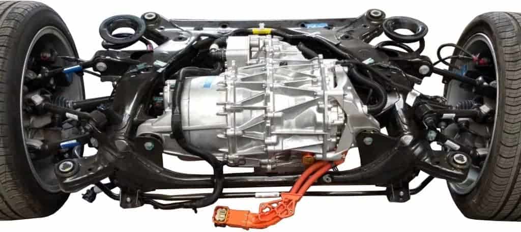
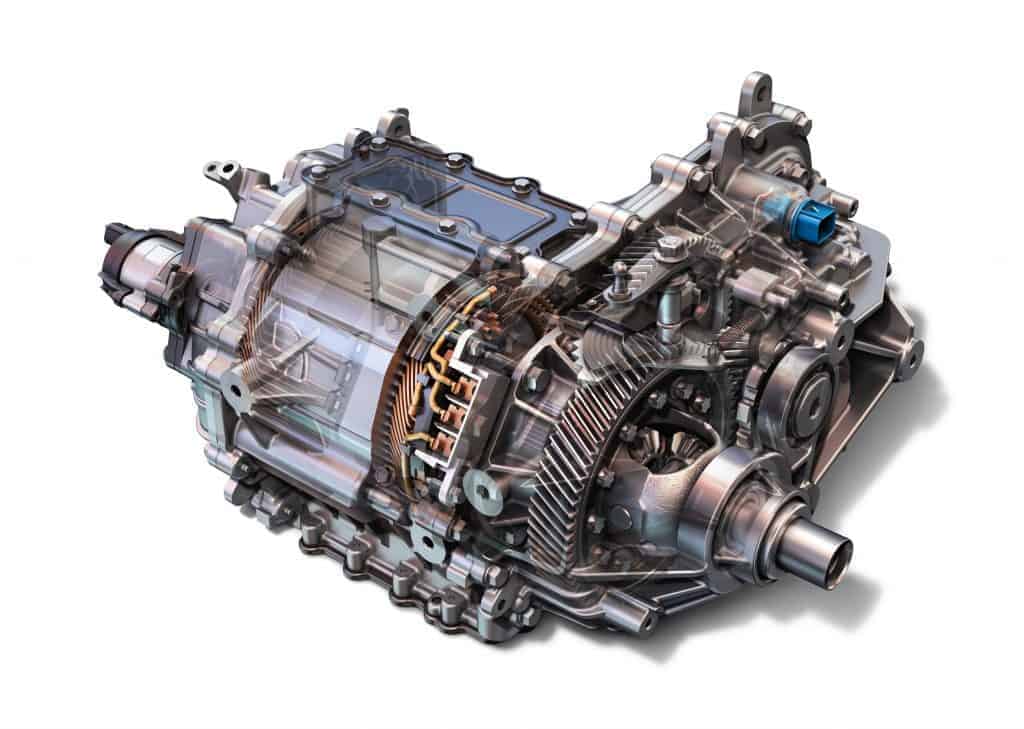
The electric motor of a fully electric car is often mounted at the height of the rear axle. The image below shows the electric motor with the inverter in a cylindrical housing and final drive of a Tesla.
AC electric motor (synchronous, with permanent magnets):
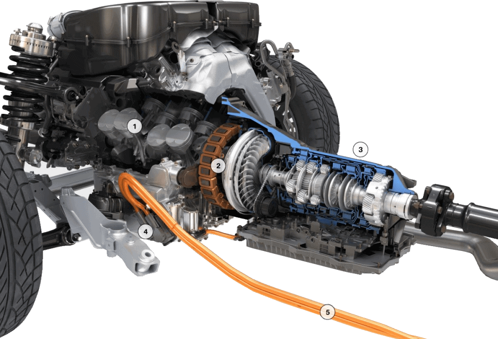
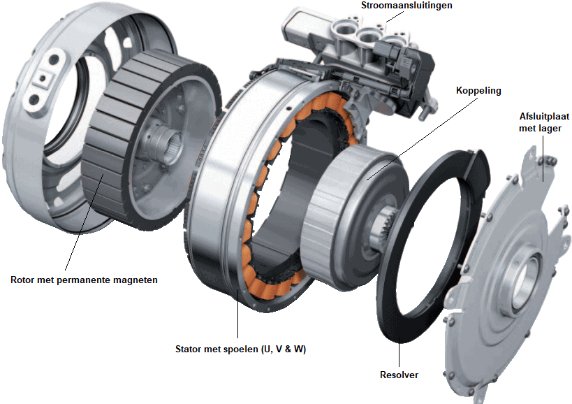
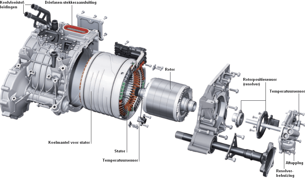
The following image shows the parts of an Audi (synchronous) electric motor. This type is used in the hybrid variants of the A6 and A8. We will briefly list the parts. These parts are described in detail in the following paragraphs.
The rotor with permanent magnets will rotate as a result of a change in the magnetic field in the stator. The rotor is connected to the clutch, which can connect or disconnect the combustion engine and electric motor (in conjunction with a clutch not shown) in different operating conditions. The position of the rotor is controlled by the resolver measured: this data is important for the IGBT drivers to drive the stator coils at the right time.
The electric motor with permanent magnets can be controlled by both DC (direct voltage) and AC (alternating voltage).
The synchronous motor is one of the most commonly used electric motors in hybrid or fully electric vehicles. This type of electric motor consists of a stator with windings and a rotor with several permanent magnets. The rotor rotates at the same speed as the stator's magnetic field. The control of the synchronous motor can be realized as follows:
- AC: Driven by a sinusoidal signal (alternating current).
- DC: is controlled with a square or trapezoidal signal (direct current)
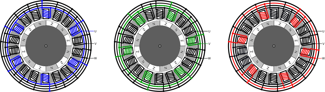
The stator of the synchronous motor is made up of three stator coil groups: U, V and W. Each group contains three sets of six coils connected in parallel and distributed over the entire circumference of the stator. Every third coil belongs to the same series.
- U Coils: Blue
- V-coils: green
- W coils: red
The rotor contains several permanent magnets. By alternately energizing coils in the stator, a rotating magnetic field is created. The rotor follows the rotating field and therefore starts to rotate with it.
AC control of the synchronous motor:
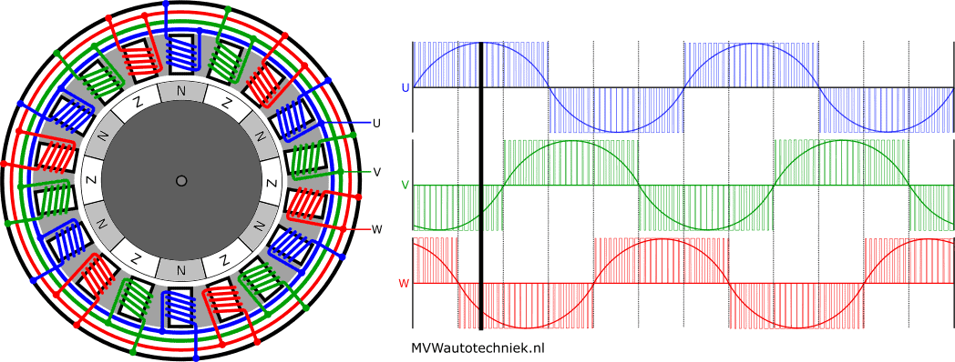
The AC control uses a variable speed drive or sinusoidal commutation. The stator coils are supplied with an alternating three-phase sine wave voltage to rotate the rotor.
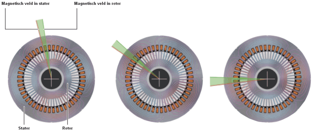
The figure below shows the rotor position at a maximum energized U-coil. Due to the magnetic field, the north poles are directly opposite the energized U-coils. The cursor in the graph next to the electric motor indicates the actuation of the coils at that moment.
For your information: the rotor in the explanation rotates when driving the stator coils clockwise.
In the following figure, the sine wave, so the alternating current through the U-coil, is maximally negative. During this drive, the south poles of the rotor are directly opposite the energized (U) stator coils.
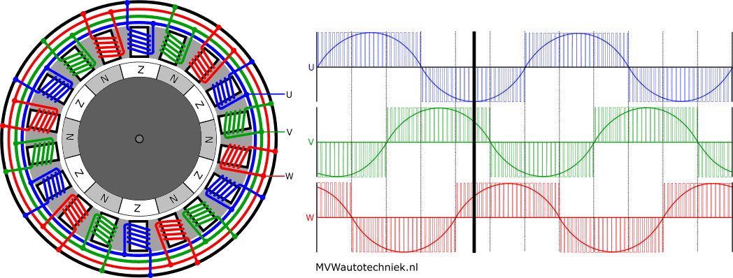
There is actually a small air gap between the north and south poles of the rotor. During the change from the south to north pole, the current direction in the U-coil reverses. Further:
- The current through the V-coil (green) is near maximum positive; the north pole is also almost opposite the coil.
- The current through the W coil has been maximally negative and is rising. The south pole has turned past the coil.
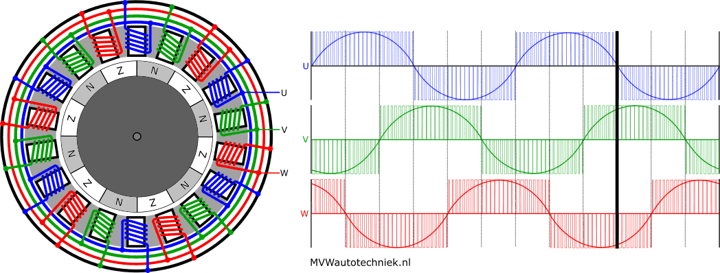
To give an impression of how the current flows, the animation below shows the rotation of the rotor due to the alternating current.
AC electric motor (asynchronous, squirrel cage motor):
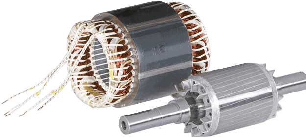
The squirrel cage or squirrel cage electric motor is an asynchronous motor. The difference with the permanent magnet synchronous motor and the asynchronous motor is in the rotor: this is a soft iron drum with conductors in the longitudinal direction. The rotor runs asynchronously with the stator, that is, there is a speed difference between the rotor and the magnetic speed of the stator. The stator is exactly the same.
The rotor of the asynchronous electric motor consists of short-circuited coils; the U-V and W-coils are connected on one side. The moment the rotor is in the stator rotating field, an induction voltage is created in the rotor coils. Because the rotor coils are shorted together, a current flows through them. This current causes the rotor to generate a magnetic field, which creates a torque. Because the operation of the asynchronous electric motor is based on the induction law, we also call it an induction motor.
The torque delivered affects the slip between the rotating magnetic field in the stator and the rotational speed of the rotor.
The asynchronous motor has a number of advantages and disadvantages over the synchronous motor.
Benefits:
- relatively simple, robust and inexpensive rotor;
- high torque at low speed.
Cons:
- lower power density (per mass) and efficiency (efficiency). The currents in the short-circuited rotor coils give rise to additional rotor losses;
- speed cannot be accurately controlled, because it depends on the load. This in itself does not have to be a disadvantage: with a good control system, the speed of the asynchronous motor can also be set;
- high starting current.
The rotor position and speed of the asynchronous motor is measured by a rotor position sensor. Hall sensors usually provide at least four pulses per revolution of the rotor to transmit the rotor position and speed. We do not call this type of rotor position sensor a resolver, as is the case with the synchronous motor.
Unlike the synchronous motor, the rotor position sensor is not needed to know the rotor position at standstill. The rotor position is important during rotation: it must be prevented that the slip between the magnetic rotating field and the rotor does not become too great. The moment the rotating field goes too fast, a situation can arise in which the rotor suddenly wants to turn in the other direction. The forces that arise here can be disastrous for the mechanical and electrical components.
Some manufacturers choose to also use an asynchronous motor resolver applying. The reason is unknown to me. In any case, the resolver is extremely accurate both when stationary and when running, which may benefit the precise control.
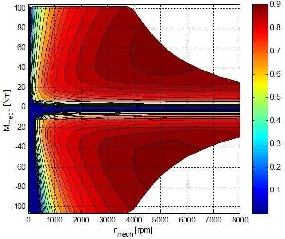
Efficiency map of the synchronous and asynchronous electric motor:
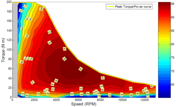
The figures below show the efficiency of the synchronous electric motor (left) and the asynchronous electric motor (right).
- The synchronous electric motor is very efficient. Efficiency is over 90% in a wide range, with peak values up to 96%. From 2000 rpm, a field weakening occurs, as a result of which the maximum torque decreases.
- The asynchronous motor has a significantly lower efficiency than the synchronous motor at lower speeds.
Related pages: