Subjects:
- Glow Plug Introduction
- Glow plug operation
- Computer Controlled Glow Plugs
- Glow plug failure
- Removing glow plugs
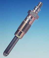
Glow plug introduction:
Glow plugs are also called glow plugs. Both names are correct, but this page only talks about the glow plug. Each diesel engine has glow plugs. An indirect injection diesel engine always needs glow plugs to be able to make a cold start. A direct-injection diesel engine can also start without glow plugs at outside temperatures above 10 °C, but then emit many more harmful substances, including soot. In addition, a diesel engine with a non-functioning good system will also be less likely to soot filter can regenerate because the required temperature is not reached.
Due to the large heat-dissipating surface of a pre- or whirl chamber in an indirectly injected diesel engine, it is necessary during a cold start to heat up the air in the combustion chamber. That happens with the glow plugs.
Glow plug operation:
When the ignition is turned on, a high current immediately flows through the cold glow plug. This current ensures that the glow plug reaches a very high temperature within a few seconds. The current decreases as the temperature of the motor increases. The resistance of the control coil increases with temperature. For example, a uniform temperature of about 1000 degrees Celsius is maintained with a glow stick with a metal glow stick and about 1400 °C with a ceramic glow stick.
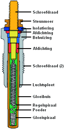
A glow plug has a glow coil and a control coil mounted in a glow tube. The filament makes the glow tube glow at the end. The filament and the control coil are firmly embedded in a powder. This powder is electrically insulating, but conducts heat well.
On modern cars, the system starts to preheat when the car is unlocked or when the driver's door is opened. At that moment it is a signal to the engine control unit that the engine will be started 'soon'. By already controlling the glow plugs, the air in the combustion chamber and thus the materials of the engine have been heated up for some time before the engine is started.
Already after about 5 sec. the glow plug reaches its operating temperature. The glow time is electronically controlled. Usually, the glow plugs remain switched on for a while after the engine has started, depending on the ambient temperature. Due to the afterglow, the engine will run evenly after a cold start and will emit less soot.
The glow plugs are also actuated during the regeneration process of the soot filter.
The images below show a direct (left) and indirect (right) injection diesel engine. On the direct injection diesel engine, the glow plug is located directly next to the injector above the piston. The glow plug of the indirectly injected version is mounted in the pre-swirl chamber.


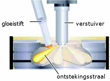
Some engines use an ignition jet. A fuel jet coming out of one of the injector holes is aimed at the glow plug. The fuel comes into contact with the hot glow plug and will therefore evaporate more quickly. A combustible mixture is created even faster, so that the engine runs better during a cold start. The illustration shows the ignition radius on a direct injection diesel engine.
Computer Controlled Glow Plugs:
With electronically controlled glow plugs, the control coil described in the previous section is omitted. The temperature is then no longer controlled by the control spiral, but indirectly by the engine management computer. This ECU determines the glow time, the glow time and the control.
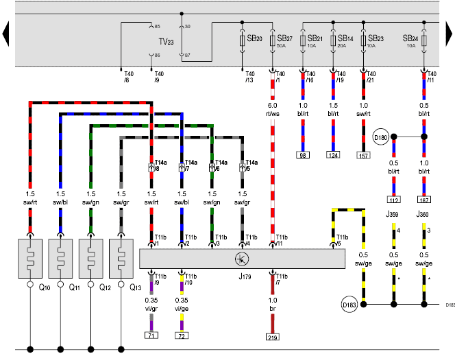
The schematic shows the components of the glow system of a VW Golf VI 2.0 tdi engine:
- J179: vending machine (control unit)
- Q10 to Q13: glow plugs cyl. 1 to 4.
The glow plugs are supplied with voltage by the automatic glow plug (J179), also called the glow control unit or the glow relay. Pin 11 and 7 of the glow plug are connected to the fuse box (plus) and a ground point on the body.
The glow plug is connected to the engine control unit via the vi/gr and vi/ge wires (at positions T11b pins 9 and 10). This ECU can be found on a different diagram with references 71 and 72.
The signal transmission or communication between the glow plug system and the engine-ECU can be done via LIN bus be established. The glow plug communicates with the engine-ECU when and for how long to drive the glow plugs, and provides feedback if a glow plug has failed, allowing the engine-ECU to store a fault.
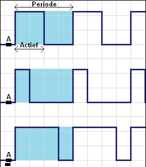
The glow plug controls the glow plugs by means of a Pulse Width Modulation (PWM) signal. The width of the pulse determines the control, and thus the temperature of the glow plugs. The wider the “active” portion of the PWM signal is in one period, the hotter the glow plug will get. The figure shows the principle of a PWM signal:
- above: 50% duty cycle;
- middle: 25% duty cycle (active a quarter of the period time)
- bottom: 75% (active three quarters of the time). The average voltage is therefore the highest of the three PWM signals shown.
In the first phase of the pre-heating process, the glow plugs are controlled with a duty cycle > 95%, which equates to an average voltage of around 13 volts. The glow plugs thus reach a temperature of approx. 1100 °C very quickly. The voltage is then reduced in steps to an average of 4 volts. The temperature drops to about 1000 °C and is then kept constant. The afterglow stops:
- after the glow plugs have been actuated for a certain period of time;
- if the coolant temperature is higher than ± 60 °C
Glow plug control at engine start:
When the engine is started, the glow regulator controls the glow plugs at a constant voltage of 12 volts for a set amount of time. This is also called the “preglow”, translated into Dutch as “preglow”. This way of controlling ensures that the glow plug reaches its working temperature as quickly as possible. This preheating time is required at a coolant temperature lower than 25°C. The lower the temperature, the longer the preglow will last.
- at a coolant temperature above 25°C, no preglow takes place;
- at a temperature of 25°C the preglow lasts 0,5 seconds;
- at a temperature lower than -25°C the preglow takes between 2,5 and 3 seconds.
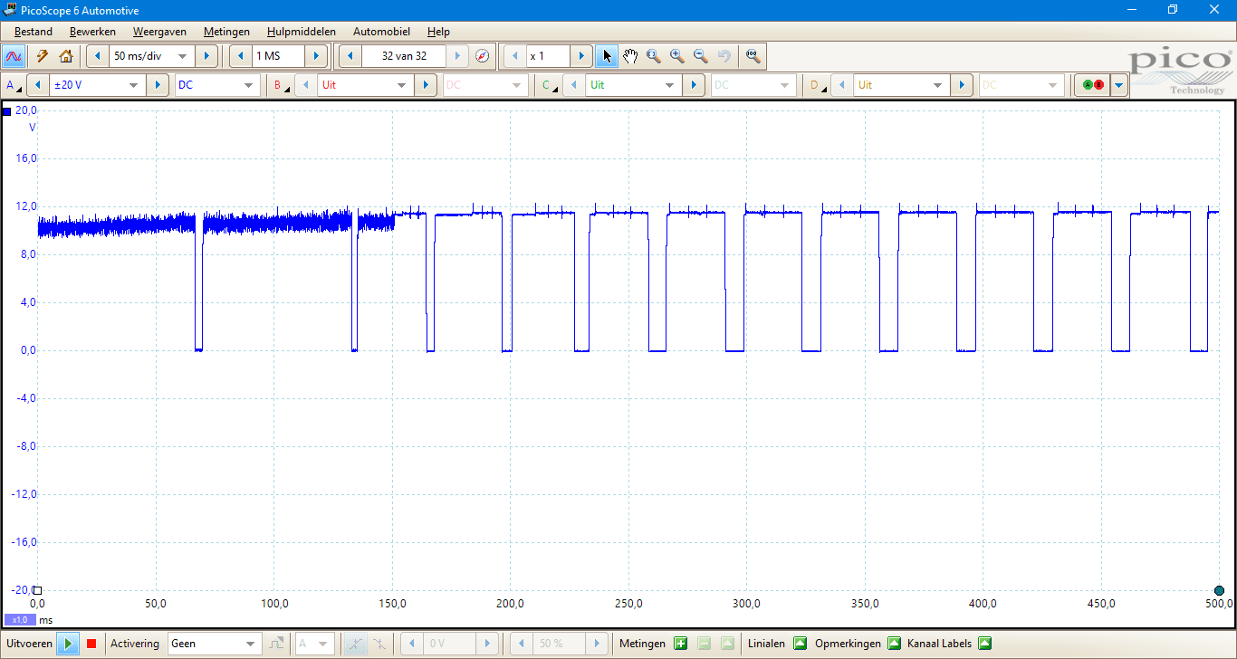
The scope images were recorded on a glow system with ceramic glow plugs (BMW 320d, N47, 2011). These heat up faster than metal glow plugs. The preglow can then take longer. After some time, the working temperature of the glow plug is reached and it is pulsed to keep it warm. This scope image shows the switched-on time (12 volts) becoming shorter and shorter over time.
Afterglow after the engine has started:
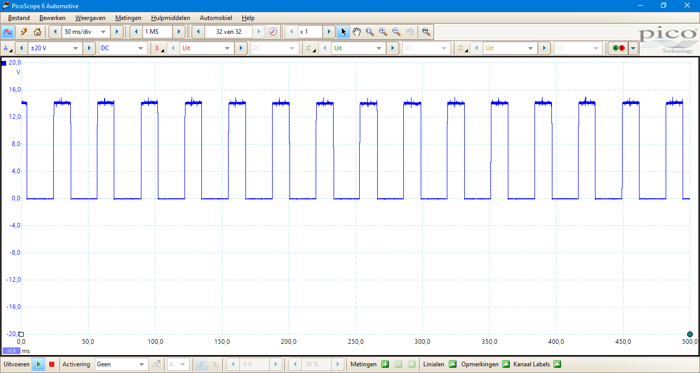
For several seconds after the engine has started, the glow control unit continues to pulse the glow plugs. This keeps the glow plugs at the right temperature for afterglow. This helps to minimize diesel knock as well as harmful emissions. The afterglow lasts until the coolant has reached a temperature of at least 60° Celsius (the actual switch-off temperature may differ per brand or version). The duty cycle remains the same in the afterglow phase.
Glow control of multiple glow plugs:
The glow control unit controls the glow plugs one at a time. With wider pulses, the pulses partly overlap. The reasons for controlling the glow plugs separately from each other are as follows:
- if all the glow plugs of the engine receive a pulse at the same time, a current will flow immediately. In that case there is an equal amount of current (with a pulse the currents through four glow plugs are added together), and if the voltage is 0 volts, no current would flow anymore. This on-off switch of a lot of power and no power would put an unnecessarily high load on the on-board network;
- by alternating the pulses between the cylinders, the current through the glow regulator remains constant, but is distributed by the pulses over the glow plugs.
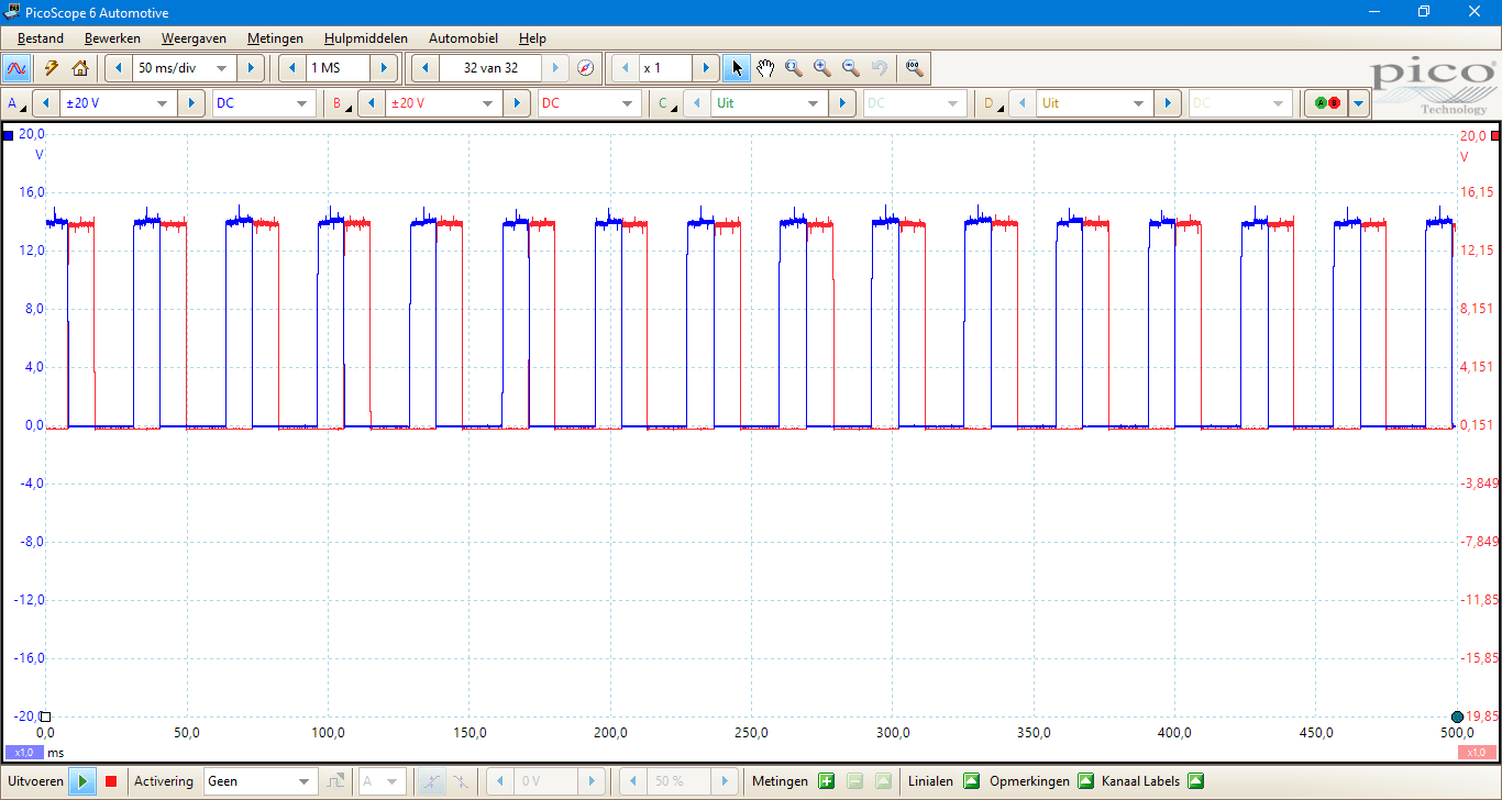
In the scope image below we see the driving pulses of two glow plugs. In this case of cylinders 1 and 2. The four glow plugs can all be controlled individually or in groups (eg from cylinders 1 and 4 simultaneously, and from 2 and 3 simultaneously).
Glow plug failures:
When glow plugs are defective, this can be noticed by speed fluctuations or a diesel knock after the engine has started at a cold start. Strong soot development follows (not noticeable when a particulate filter is fitted). A consequence of one or more defective glow plugs can also ensure that the soot filter can no longer be regenerated. The required temperature is not achieved and is saturated by an excessive amount of soot particles. Defective glow plugs are recognized by the engine management in modern systems. The glow control unit always performs a resistance measurement (via a voltage drop across a shunt) and communicates the condition of the glow plugs (often via LIN bus) to the engine control device. A fault message will often only be displayed on the dashboard at low outside air temperatures. At temperatures above 5°C to 10°C, a malfunction is stored that you can OBD system can read out, but the driver is not alerted by a message on the dashboard.
If a glow plug is suspected to be defective, a multimeter a resistance measurement is performed. The measurement can be performed with the glow plug in the engine block, but also on a disassembled glow plug. In view of the risk of damage when dismantling glow plugs, it is wiser to measure the glow plugs in the installed condition in the first instance.
- remove the glow plug plug and set it aside;
- place the red test probe on the head of the glow plug to which the plug is supposed to be connected;
- place the black test probe (preferably) on the glow plug housing, elsewhere on the engine block, or at a suitable ground point;
- set the multimeter to the “ohm” position to measure the resistance.
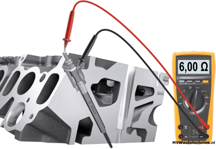
The resistance value does not indicate how good a glow plug is. After all, the resistance through the coil is measured. The metal or ceramic end may be soiled, or glow less quickly and properly due to age. However, the resistance measurement can be used to determine whether the glow plug is capable of glowing as soon as current flows through the coil:
- a resistance between 0,2 and 6 Ω is good;
- a resistance < 0,2 Ω is too low. Most likely the coil (plus) and housing (ground) make internal contact with each other;
- no resistance (OL or 1.) means there is an internal break in the glow plug. No current can flow through the glow plug;
- a very high resistance (eg 6 kΩ) also indicates a defect. As a result, the amperage will be small and the glow plug will hardly heat up.
If it appears that one or more glow plugs have an incorrect resistance value, but all four glow plugs are of the same age, the manufacturer's advice is to replace all glow plugs at the same time. Even if a resistance measurement turns out well, the glow properties can be less due to age. With four new glow plugs it is ensured that there are no mutual differences in glow properties and thus in glow temperatures.
Glow plugs that are pulse-driven by an automatic glow plug can be recognized by the voltage on the housing: 5,3 resp. 7 volts. This is the operating voltage needed to keep it warm. Where glow plugs from old engines with a 12 volt battery could be tested, the newer type glow plugs can overheat and malfunction if they are fed with 12 volts for too long.
Removing glow plugs:
When removing the glow plug, make sure that it can be unscrewed with little force. Excessive effort can damage the thread or cylinder head, or break the glow plug. To prevent this, it is recommended to bring the engine up to operating temperature first. By heating the materials of the glow plug and the cylinder head, the baked-on soot particles become soft. The glow plug will now be easier to disassemble than with a cold engine.
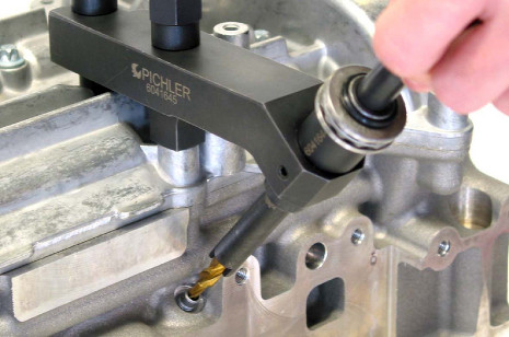
When the glow plug breaks, in many cases a hole has to be drilled in the glow plug and then the threads and the remaining head removed from the hole or from the cylinder, possibly using a magnet. There is a risk that the screw thread will be damaged during drilling if you do not drill accurately. Auxiliary tools exist to drill carefully at the right angle (see the picture below). In the most annoying situation, one has to disassemble the cylinder head to remove the glow plugs. Leave the replacement of a glow plug to a specialist.

The most common cause of a glow plug breaking is that it was overtightened in the past. Glow plugs have a tightening torque between 10 and 25 Nm, depending on the thread. Always refer to the workshop manual or the specifications of the relevant glow plug for the correct tightening torque.