Subjects:
- General
- Throttle valve with a monopoint injection system
- Throttle valve with a multipoint injection system
- Idle Control
- Throttle control on larger engines
- Throttle Position Sensor
- Electronic throttle (throttle by wire)
General:
Every gasoline engine has a throttle. The throttle valve allows to control the amount of air entering the cylinder. Diesel engines also have a throttle valve, but it is always fully open when the engine is running. That's because a diesel engine runs on a surplus of air. The throttle on the diesel engines only serves to let the engine stall; when the valve closes, the air supply is shut off. The engine then immediately shuts off. The fuel supply is therefore stopped. In a diesel engine this is also called the throttle valve instead of the throttle valve. In fact, a throttle on a petrol engine is also a throttle: the air is throttled under all conditions except full load.
The following chapters on the monopoint and multipoint injection systems are, of course, about petrol engines.
Throttle valve with a monopoint injection system:
For single injection engines (monopoint injection system) one injector is mounted in front of the gas valve. This injector injects the fuel directly onto the throttle. This technique is old and is no longer applied to new cars. This is because this system has a number of drawbacks. Because the injector injects into the gas valve, it mixes with the air there. The intake manifold is divided over 4 or more cylinders. The amount of fuel will not always be exactly the same in all cylinders. For example, cylinder 1 gets the most fuel in the air, while cylinder 4 gets a lot less. As a result, the system is hardly or not at all controllable. The use of monopoint is therefore unsuitable for meeting current environmental requirements.
Nowadays, several injectors are used that inject exactly the same amount of fuel per cylinder. The amount can then even be regulated per cylinder. This is what we call it multipoint injection system.
Throttle valve on a multipoint injection system:
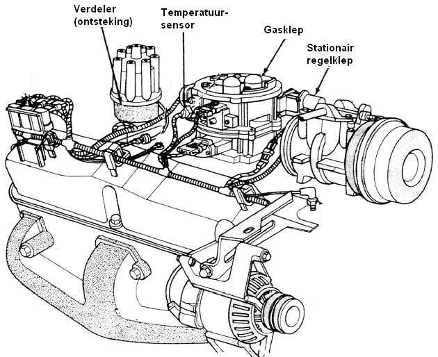
In the engines with multiple injection (multipoint injection system), the injectors for indirect injection are mounted in the intake manifold after the throttle valve. The injectors spray onto the engine's intake valves. With direct injection, the injectors inject directly into the combustion chamber. Both the indirect and direct injection engines have a throttle body mounted as shown below. Exceptions are engines with Valvetronic (BMW) and Multi-air (Fiat). The throttle body is mounted between the intake manifold and the tube with the air mass meter. This can be controlled electrically using an electronic accelerator pedal (drive by wire) or with a throttle cable (bowden cable).
The engine management systems in use today use throttle position control. An adjusting motor on the throttle ensures that the position of the throttle can be changed. This can be for the cruise control or for the idle control. Potentiometers measure the throttle position. The engine control unit (the ECU) receives the values from the potentiometers and can then control the actuators to open or close the throttle more.
Idle Control:
To accelerate, the accelerator pedal is pressed. The gas valve opens to allow a greater amount of air to be drawn in. When decelerating or idling, the accelerator pedal is not actuated; here the throttle is closed. In order to still get an air passage, a stationary regulation is applied. The idle speed is kept as low as possible by the engine management system. The lower the idle speed, the lower the fuel consumption and engine wear. The idle speed should not be too low; this will cause erratic running of the engine and the possibility of it stalling. The desired idle speed is not always the same. The temperature of the intake air, the air conditioning switched on, the position of the clutch pedal or automatic transmission selector lever affect the idle control. The stabilization of the speed control can be achieved in several ways:
- filling degree regulation. It is most often used in combination with adjusting the ignition timing.
- change mixture composition. This has a negative influence on the exhaust gas emissions and the control range is limited.
- adjust ignition timing. This also has a negative impact on emissions, but allows extremely fast control.
- adjust valve timing. This provides an extra control option on top of an already existing filling degree control.
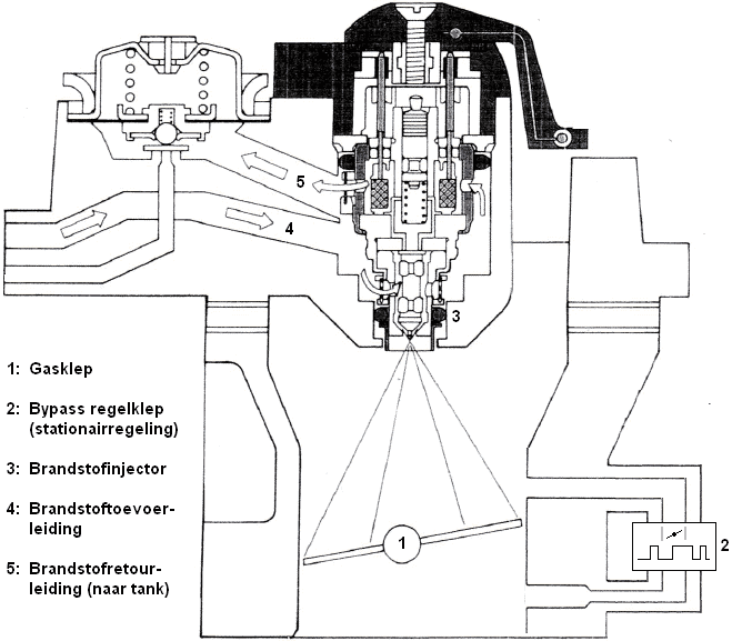
Fill level control uses a by-pass valve that allows air circulation outside the throttle, or adjustment of the throttle.
By-pass valve:
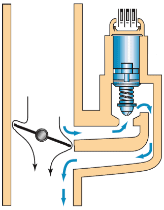
A bypass valve opens or closes the air supply outside the throttle so that the idle speed is stabilized. In the image below, a partially open throttle can be seen on the left. On the right side, an open by-pass valve allows air to be drawn into the by-pass duct by the engine. When the throttle opens further, the by-pass valve will close. After all, the by-pass is only necessary when the throttle is closed. The engine management system determines how far the bypass valve should be opened. The throttle position sensor, which indicates the opening angle of the throttle valve, together with the air temperature sensor provides the necessary information.
The by-pass that is often used is a pulse width modulated spring loaded solenoid valve. The motor management system supplies the solenoid coil with a PWM signal. By varying the duty cycle, the valve can be opened, closed, or set to any position in between. The by-pass valve may also be provided with a stepper motor.
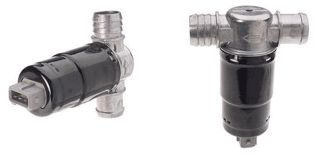
Pulse width modulated bypass solenoid valve:
The figure shows two views of a PWM controlled bypass valve. Judging by the three pins in the plug connection, this is usually a version with two coils; one to open the cover and one to close.
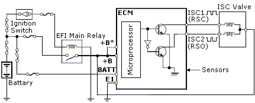
The diagram below shows the control method of the two coils. When the “EFI Main Relay” (relay for the engine management computer) is switched on, the microprocessor is supplied with voltage. Two transistors are controlled in the ECU.
The way of switching allows the lower transistor to invert the PWM signal from the upper one. The PWM signals are mirrored. This is seen at ISC1 and ISC2 (the outputs of the ECU). The ECU varies the duty cycle for each coil. The difference in strength between the two magnetic fields determines the position of the valve. The frequency is between 100 and 250Hz.
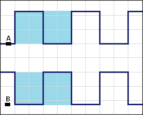
De duty cycle control can be measured with the oscilloscope. In the picture below, the valve is half open (duty cucle 50%). On ISC1 and ISC2, the positive and negative pulse are equal to each other.
Pulse Width Modulated Spring Loaded Bypass Solenoid Valve:
In addition to the servomotor with two coils, it is also often equipped with one coil. In that case, there are often two pins in the plug connection: for the PWM control and a ground wire. A spring ensures that the valve is closed at rest; this makes the second coil superfluous.

Bypass performed with stepper motor:
In addition to the PWM-controlled bypass valves, there are also valves that are adjusted by means of a stepper motor. The ECU controls the coils. Click here to go to the stepper motor page.
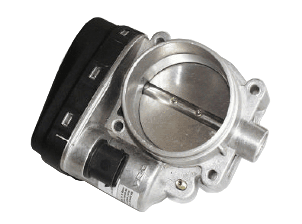
Throttle body with actuator:
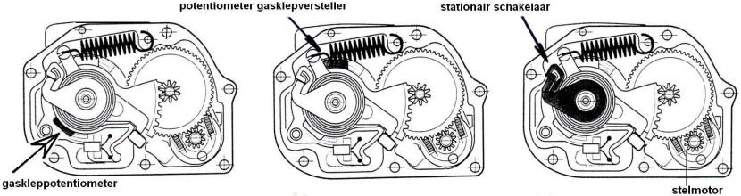
Modern engine management systems use throttle position control to stabilize idle speed. A separate bypass valve no longer needs to be used. All components for the throttle position control are housed in the housing. Two potentiometers record the throttle position for the entire angular rotation (center of the picture). Together with the idling switch, which registers the idling (left), the signals are sent to the ECU. By means of a PWM signal, the DC or DC motor in the throttle is driven to control the position of the throttle. Here too, there is the possibility that a stepper motor causes the throttle to rotate.
The inside of the throttle body is modified so that the air gap increases linearly with the angular rotation of the throttle. This listens very accurately. It is therefore important that the throttle valve position is set to the basic settings after replacing or cleaning the throttle valve with diagnostic equipment.
Throttle control on larger engines:
With large engines, such as the V12 engine from BMW (shown in the picture below), the air supply through one throttle valve is too small. At full load, the engine needs so much air that the diameter of a single throttle valve would be too small. There are therefore two throttle bodies mounted. One for each cylinder row. This version includes two air filter housings, two air mass meters and two suction pipes.
Throttle Position Sensor:
In a throttle body there is a throttle position sensor which transmits the position of the throttle valve to the ECU of the engine management system. The position of the throttle determines the amount of air drawn in, and therefore also the amount of fuel to be injected. On the basis of the throttle position, the ECU can adjust the idle control to the operating conditions: with a cold engine or with air conditioning switched on, the idle speed should be increased slightly, so the throttle should open a little further. See the paragraph: idling control.
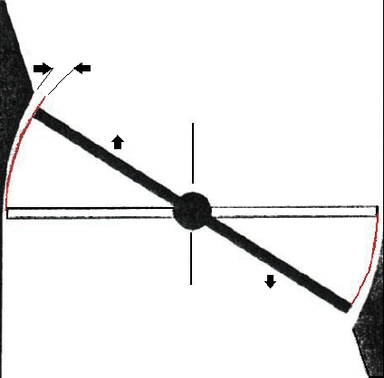
In the following diagram we see an ECU and a potentiometer which are connected with three wires. The potentiometer has a mechanical connection to the throttle valve. A twisting of the throttle will result in a displacement of the runner.
- At pin 3, the potentiometer receives a supply voltage of 5 volts;
- The potentiometer is connected to ground at pin 1;
- The signal from the potentiometer is sent to the ECU via pin 2: the runner (the arrow) is attached to this wire.
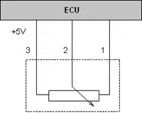
The position of the bishop on the carbon track of the potentiometer determines the output voltage. When the runner is positioned to the far left, the output voltage is high: the current only has to travel a short distance across the resistor, so less voltage is absorbed. The further the cursor moves to the right, the lower the signal voltage will be. On the page: potentiometer It goes into more detail about how it works.
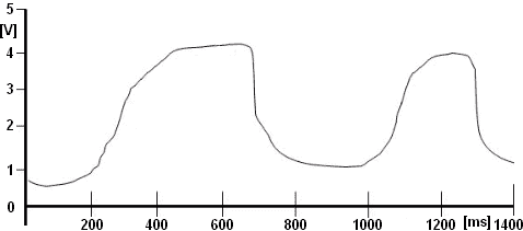
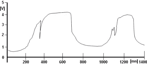
With a multimeter you can measure the supply voltage in relation to the ground. This should be a stabilized voltage of 5,0 volts. It is better to measure the signal voltage with an oscilloscope: disturbances can occur in the AM signal that are not visible with a multimeter measurement. The two drawings below show a correct signal (smooth lines) and a signal with interference, where the signal shows a noticeable voltage drop within a very short period of time.
In English, but sometimes also in Dutch literature, we often see that the abbreviation “TPS” is used. This stands for: “Throttle Position Sensor”, which is a translation of the Dutch “Throttle Position Sensor”.
Electronic throttle (throttle by wire):
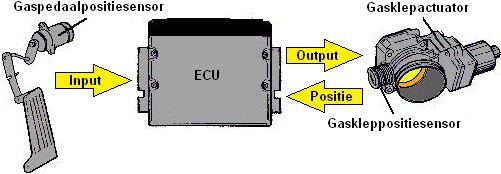
Nowadays the throttles are electronically controlled: we no longer find a (mechanical) cable between the accelerator pedal and the throttle. The position of the accelerator pedal is registered by two position sensors and sent to the ECU of the engine management system. The ECU checks whether the signals are plausible by comparing them to each other and controls the throttle actuator (actuator motor) to make the valve take a predetermined position. We call this “throttle by wire”, in Dutch: throttle control via wiring.

The accelerator pedal position sensors are mounted in the housing or on the top of the accelerator pedal. The signals from these sensors must be extremely accurate and reliable: under no circumstances do we want a signal failure to cause unintentional throttle throttle or the engine to stall. To ensure reliability, manufacturers fit two position sensors please:
- Manufacturers can choose to transmit the signals from both sensors at different voltage levels. When the signal voltage from sensor 1 increases from 1,2 to 1,6 volts, the signal voltage from sensor 2 will also rise 400 mV, but then from 2,2 to 2,6 volts;
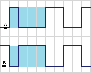
- Another possibility is to mirror two identical signals to each other: The scope image below shows this strategy. When the accelerator pedal is actuated, the signal on channel A (blue) rises from 800 mV to 2,9 volts and the signal on channel B (red) drops from 4,3 to 2,2 volts. The signal curve of the Amplitude (AM signal) is exactly the same, but mirrored.
The moment one of the two signals has a disturbance: the signal drops to ground for a moment or shows noise, then a difference is seen in both signals. The ECU can then decide to go into emergency mode: the accelerator pedal position is no longer reliable. In emergency mode, a limited power is available, with which you can drive to a safe place along the road or to the garage at a reduced speed.
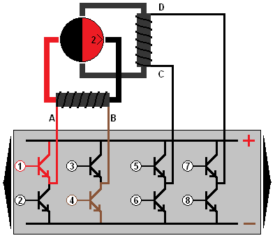
The throttle is controlled by a DC electric motor opened and closed. The throttle adjustment motor is controlled by a H-bridge controlled. The actuator, like the accelerator pedal, is equipped with two potentiometers. The two images below show the throttle control motor (3) with two options of the double potentiometers:
- Potentiometers with wipers pointed upwards: both signals are identical, but at a different voltage level;
- Potentiometers with the runners opposite each other: signals are mirror images. If one signal becomes high when the throttle valve is opened, the other signal decreases.


On the page H-bridge the control methods of the electric motor are described. On the page Potentiometer The operation and measurement of the position sensor is discussed in detail.