Subjects:
- General
- Mechanically driven petrol pump
- Electric booster pump
- Fuel Pump Error Symptoms
- High Pressure Fuel Pump
General:
The fuel pump is part of the fuel system. The applied components are described on the page fuel system petrol engine.
Three types of fuel pumps can be used in a vehicle with a petrol engine: the mechanically driven pump, electrical booster pump and the high-pressure fuel pump. This page describes the operation and application of each pump.
Mechanically driven fuel pump:
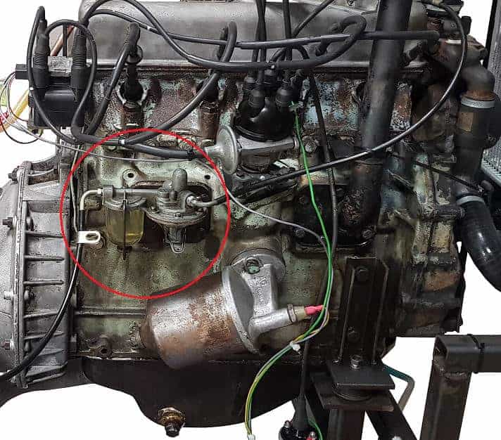
For petrol engines fitted with a carburettor, a mechanically driven petrol pump was often used. The image shows the mechanically driven fuel pump of a classic Land Rover engine from the 70s, where in 2017-2018 a conversion project to a computer-controlled engine management system has been applied to. The fuel pump is circled in red.
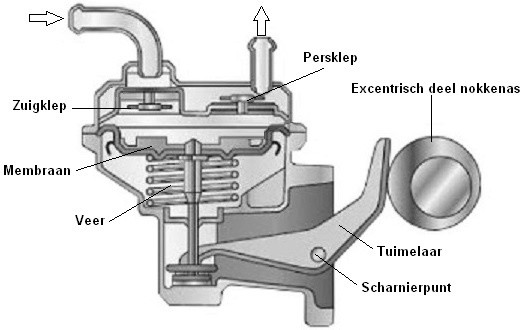
The drive takes place by an eccentric which is operated by the camshaft. Operating the rocker arm causes the diaphragm to be pulled down in the middle. The negative pressure in this space causes the suction valve to open. The fuel flows through the suction valve into the fuel chamber. As soon as the eccentric part of the camshaft continues to rotate, the spring pushes the diaphragm back into place. The overpressure in the fuel chamber causes the discharge valve to open and the fuel leaves the pump with increased pressure. The fuel pump enters the carburetor through a pipe.
When the car has been standing still for a long time and/or the float chamber is in the carburettor If there is insufficient petrol, the petrol can be pumped up with a lever on the mechanical fuel pump. The lever, like the rocker arm in the picture, is connected to the diaphragm. This is not visible in the image.
The petrol pumps are often equipped with a sight glass that also serves as a sedimentation chamber. This sight glass must be cleaned regularly. The carburettor and mechanical fuel pump system, especially the long suction line versions, are prone to vapor lock (vapor bubble lock).
Electric booster pump:
Vehicles with electronic injection use an electric booster pump. The fuel pressure is a lot higher: 3 bar with the electric pump compared to 0,3 bar with the mechanical fuel pump; so ten times higher. The pump also switches on immediately when the ignition is switched on. The fuel system is therefore immediately brought to the right pressure before the engine is started.
Today, the electric fuel supply pumps are located in the fuel tank. Sometimes they are placed outside the tank, namely between the tank and the fuel rail. The advantage of mounting in the tank is that the pump is cooled by the fuel in which the pump is located.
A two-stage pump is shown below. It is now in every car. These pumps contain two mutually independent pumps, namely the impeller pump (left image) and the gear pump (right image). Both pumps are controlled by separate electric motors. The first stage carries the fuel from the tank through the filter to the buffer reservoir. This has a capacity of about 600 milliliters. This internal reservoir ensures that when a car makes a long turn with a low fuel level, the gear pump (2nd stage) is still supplied with fuel. If the reservoir were not filled, all the fuel would go to one side of the tank, so that the pump can no longer draw in. This is prevented.
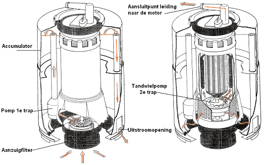
The fuel contained in the buffer reservoir is fed to the engine by the gear pump under a pressure of up to 3 bar (via the pipe at the top connection point). This is good for a pump output of 80 liters per hour. This is, of course, much more than necessary. Why this is done is explained in the text below the image.
The pump delivers much more fuel than the engine actually needs. This was done deliberately, because the system must always be under pressure. If the system were without pressure, the fuel in the pipes could heat up due to outside influences. Vapor bubbles can then form (vapour bubble lock). This is prevented by keeping the system under constant pressure. This means that not all fuel that is pumped forward is actually used. A return line has therefore been installed. The pressure regulator takes care of this. This fuel return line runs from the engine compartment back to this fuel pump. The return fuel is returned to the tank.
The pump therefore always runs at a constant speed. While the engine is idling, or when delivering power, the booster pump will always pump the fuel to the engine under the same fuel pressure. When the engine is idling, more fuel will flow back to the tank than when the car is accelerating.
Fuel Pump Error Symptoms:
The electric fuel pump ensures that the fuel is pumped from the tank to the engine. When the pump no longer works, the engine will therefore not be supplied with fuel. It is not always immediately clear that the fuel pump is no longer functioning properly. The fuel pump still works in some cases, but no longer reaches the desired pressure. The following symptoms can occur if the delivery pressure is too low:
- The maximum engine power decreases.
- Cylinder overturning takes place.
- The engine does not start properly when starting.
- Error codes are stored in the ECU.
In many cases, a low pressure fuel sensor is fitted on the supply line. This sensor sends the value of the fuel pressure to the ECU. In the event that the fuel pressure is too low, the ECU will store an error code. If no pressure sensor is present, the technician should connect a pressure gauge to the fuel gallery in case of problems. The pressure gauge indicates the current fuel pressure. The technician can then determine, based on the reading, whether the correct pressure is being achieved or whether the pressure remains too low.
A fuel pressure that is too low does not immediately mean that the fuel pump is defective. With a supply voltage that is too low, a bad ground connection or a bad plug connection, the pump can also receive insufficient voltage to work properly. If the fuel pressure is too low, it is therefore advisable to measure the voltage at the plug of the pump while it is running. In this case, never remove the plug to measure, because this will break the circuit and a contact resistance will not result in a voltage drop!
Example:
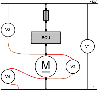
There is a contact resistance present in the positive wire. Immediately V4 measurement (see diagram) you can find out. For example, the V3 (voltage drop in the plus) indicates 4 volts. This means that the pump has 4 volts less to operate, and therefore only functions at 12 volts at a supply voltage of 8 volts (measurement V2). When the plug is removed from the pump, the circuit is interrupted and the contact resistance will no longer cause a voltage drop. In that case, 12 volts is measured in the plug. Thus, there is only a voltage drop at a closed circuit and switched on consumer, so the plug may be used while measuring did not be removed from the pump. Another possibility is to measure with the plug disconnected under load by, for example, a separate lamp.
High pressure fuel pump:
The high-pressure fuel pump of a high-pressure injection gasoline engine is almost always driven by the engine's camshaft. The pump is then on top of the valve cover and is easy to reach. The pump can easily be disassembled for repairs (first depressurize the fuel rail). The pump does not operate on “timing” as with a high pressure pump (line pump) of a diesel engine.
The picture is of a V8 engine with 8 injectors. The fuel pump is mounted on the valve cover (the valve cover is not visible in the picture). The fuel is supplied from the feed pump in the tank at a pressure of 4 bar to the two high-pressure pumps via the fuel supply line (5). When the camshaft pushes the plunger in the fuel pump, a pump stroke is made. The fuel is now pressed into the line (9) under high pressure. Through this line, the fuel enters the fuel rail (also called fuel gallery), where it is distributed under equal pressure over the high-pressure lines (7) of each injector.
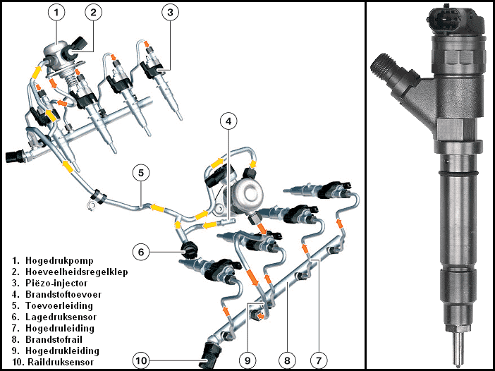
Each injector has a plug connection. This connects each injector to the engine control unit (ECU). The ECU determines according to the core fields (which are calculated with the input signals such as temperature sensors and speed sensors) when and for how long the injector injects. The injection pressure is often around 200 bar with a maximum pressure of around 250 bar (depending on brand/type).
There is always a rail pressure sensor on every fuel rail, which constantly monitors the pressure in the rail. This data is sent to the ECU, which uses this data to control the high-pressure fuel pump. The ECU then determines whether the pressure of the fuel pump should increase, decrease or remain the same.
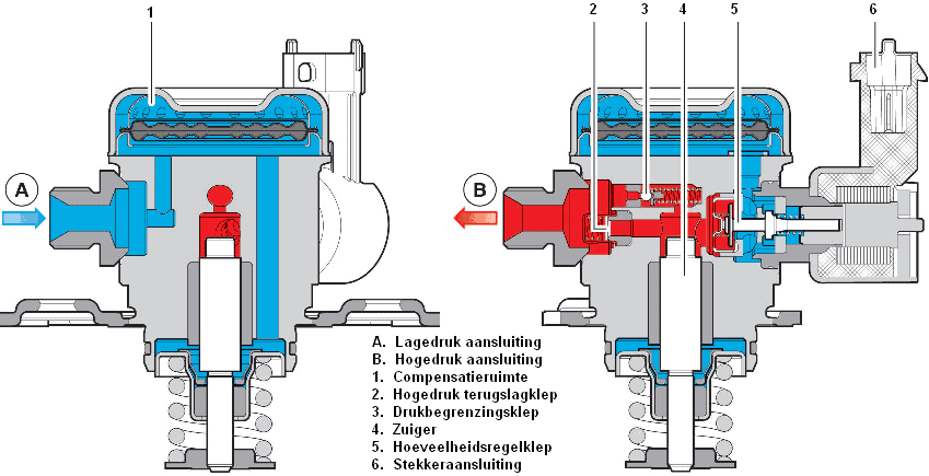
The fuel from the feed pump enters the tank via low-pressure connection A. This fuel enters compensating space 1. The fuel enters the fuel chamber via the quantity control valve 5.
The piston 4 is driven by the camshaft. The piston is in the lowest position (in neutral position) because the spring forces it downwards. The camshaft pushes the piston upwards against the spring force. The fuel is pressed into the line (via connection B) by the high-pressure non-return valve. The pressure limiting valve (3) opens if the injection pressure is too high. When this valve is (partly) opened when the piston builds up pressure, the fuel partly returns to the fuel chamber. The pressure is then reduced, because with a fully open valve, the fuel pressure in front of and behind the piston is equal. From connection B, the fuel arrives via the fuel rail at the injectors, which inject the fuel at the end of the compression stroke.
Click here to go to the page of the high pressure diesel engine fuel pump to go.