Subjects:
- Preface
- Components in an ECU with explanation
Preface:
This page explains what the components in an ECU are for. Most of the text and images were composed by Mr. W. Tulp for his own lessons and is published here with his permission.
A passenger car / commercial vehicle Technical Specialist must have the knowledge and skills to make diagnoses. Under the heading “Diagnosis technology” on this website you can find information about measurement techniques, signal processing of sensors and various cases. The information on this page deals with the operation of the components in the ECU, with the Peugeot / Citroën engine control unit as an example.
Components in an ECU with explanation:
This page currently contains a brief explanation of the components shown in the figure on the ECU PCB.
Soon there will be a more detailed explanation of the components that can be found in this ECU.
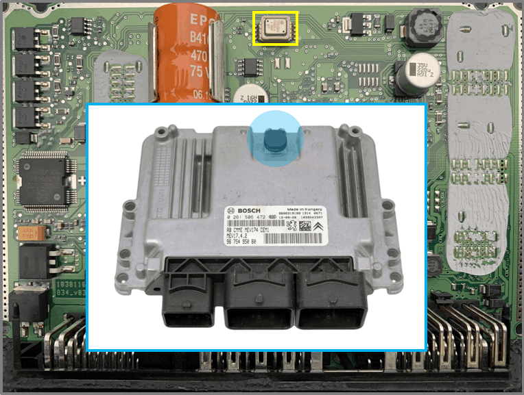
SMD284 pressure sensor:
- Surface mount piezeresistive silicon absolute pressure sensor 60 – 115 kPa
- Pressure sensor of the (atmospheric) outside air pressure. The sensor measures the air pressure through an opening in the housing (see photo).
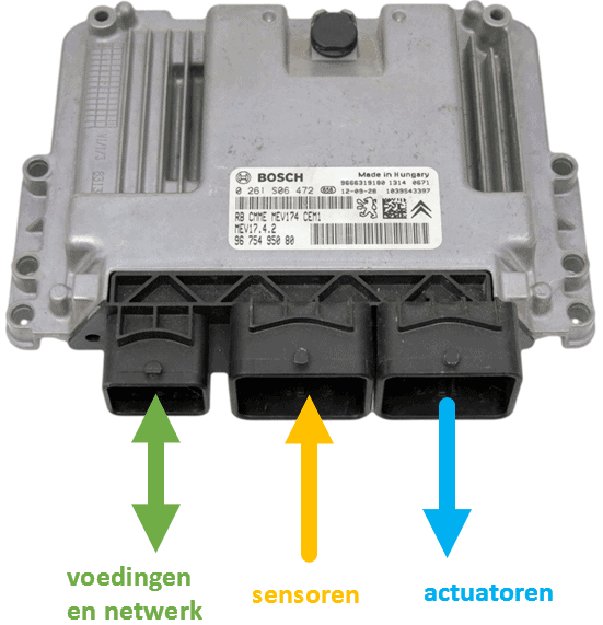
Connection plug:
- sensors:
– thin connections
– low currents - actuators:
– thick connections
– large currents - power connections
- networks
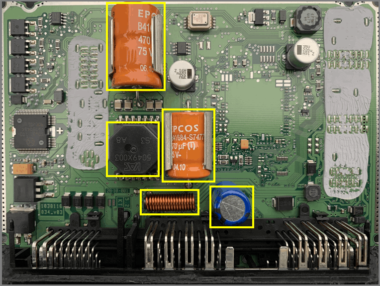
- capacitor 1
– 470uF
- 75 V
security in combination with? - capacitor 2
– 470uF
- 35 V
smoothing capacitor - coil
– emc filtering
– induced voltages - VAC 5049X003 (thanks to ACtronics)
– switching power supply transformer
- supply voltage for injectors
- Op amp LM2904
– function unknown
– in the vicinity of another circuit
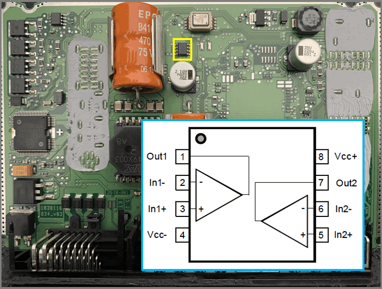
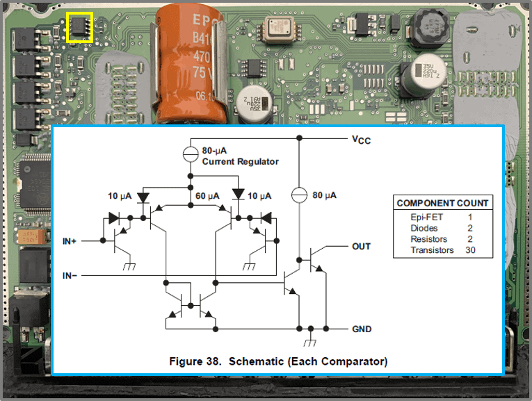
- Op amp LM2903
– comparator
– comparator of two voltages
– internal scheme
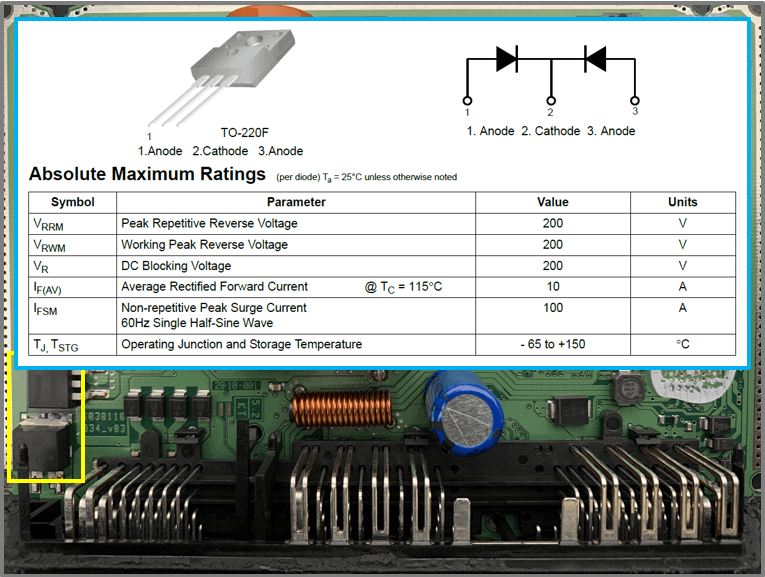
- Rectifier F20UP20DN
– Ultrafast Recovery Power Rectifier
– Ultrafast: <45 ns
– Max. current: 10 A
– go to plugs: C1, D1, E1, F1
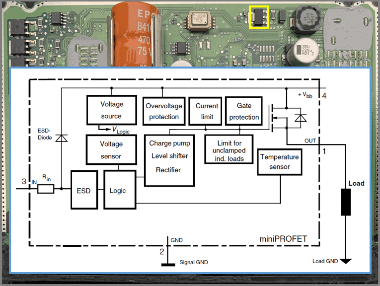
- Protection circuit against:
- short circuit
- high temperatures
– high currents (overload)
– over and under voltage
– electrostatic discharge
– reverse battery connection - Applications:
– μC mains switch for grounded 12 volt load
– for all types of resistive, inductive and capacitive loads
– replaces electromechanical relays and discrete circuits
Inflammation and injection:
- DA36FJ: four FETs under each other, go to the ignition coils according to the scheme
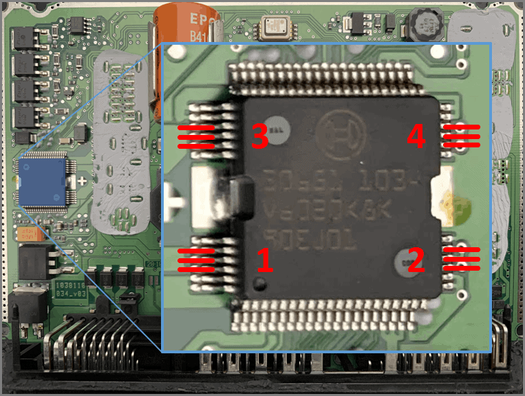
- Below these FETs is the IC: 30651 (Car injection drive chip)
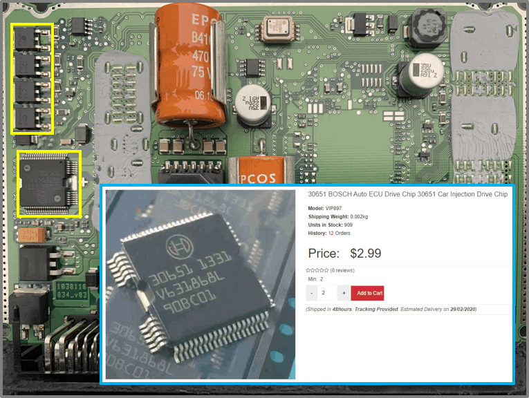
Car Injection Drive Chip:
- Three connections per injector on IC
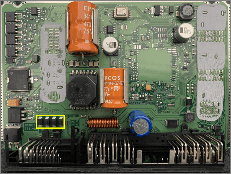
Diodes:
- Model ED08
- anode goes to the injectors
- cathode is switched on plus together
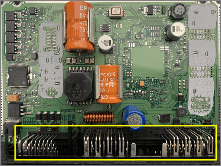
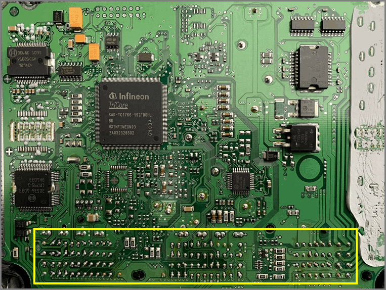
Bottom ECU. Boxed: solder connections of the connection plug
Custom-made IC:
- type 30536
- OEM: Original Equipment Manufacturer (made especially for manufacturers)
- Integrated output stages
- Control ignition coils and / or control heating lambda sensors.
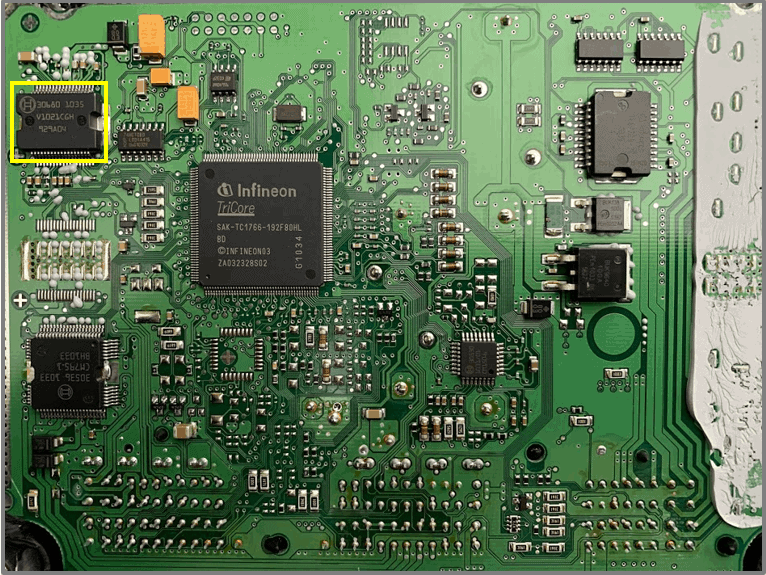
Custom IC (2):
- type: 30680
- power supply for ECU electronics
- 5,0 and 3,6 volts
- three times protected 5,0 volt sensors
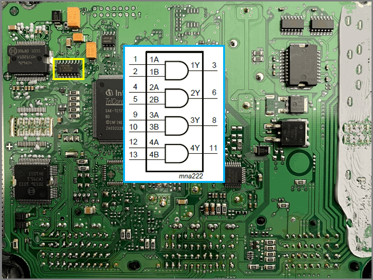
Digital IC
- type: 74HCT08
- AND gates
- IC30680 with logic data
Car ECU driver car CPU programmer accessories
- type: 30530
- in PDF datasheet (page 4 of 117): Dedicated Emulation Device chip for multi-core debugging, tracing and calibration via USB V1.1 interface available (TC1766ED)
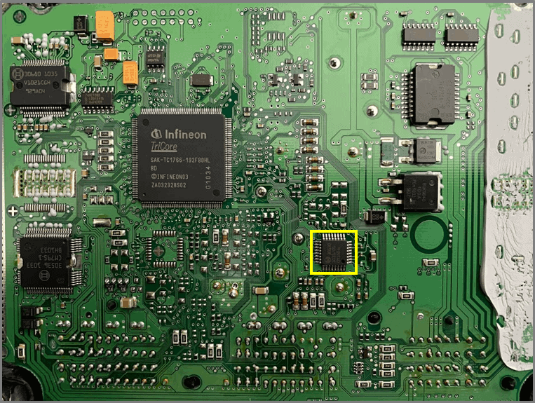
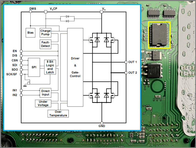
Electric motor control:
- Type: TLE7209
- H-bridge
- M29 DC Throttle Stepper Motor Driver
- The H-bridge is secured against:
- high temperatures
- short circuit
– span - All of the above faults will open the FETs (Tri-state)
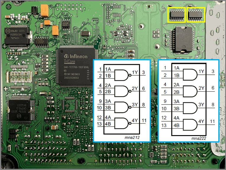
H-bridge control from M29:
- 74HCT00
– digital IC
– NAND gates - 74HCT08
– digital IC
– AND gates
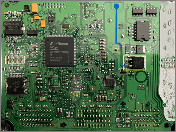
FET–BUK9640
- Function of FET is unknown
- One side is connected to ground
- Connection to the plug cannot be found
- Power circuit to ECU is marked in blue in the illustration.
FET–BUK138
- Constant power to pin 21 in the main plug.
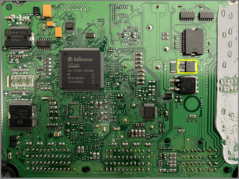
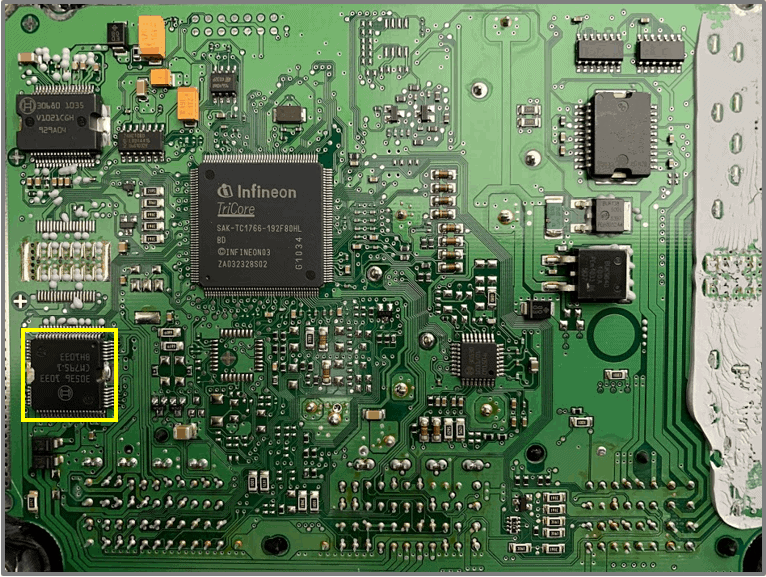
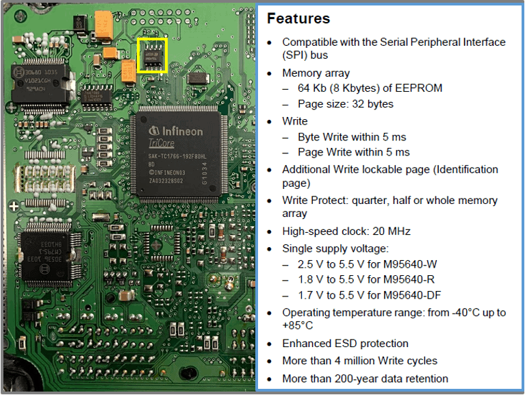
EEPROM
- 64-Kbit serial SPI bus EEPROM with high-speed clock
- Model: 95640W
- SPI: Serial Peripheral Interface (Serial interface (master/slave)
– Advantages: simple hardware, no need for addressing, low energy consumption
– Disadvantages: no slave checking, no error checking
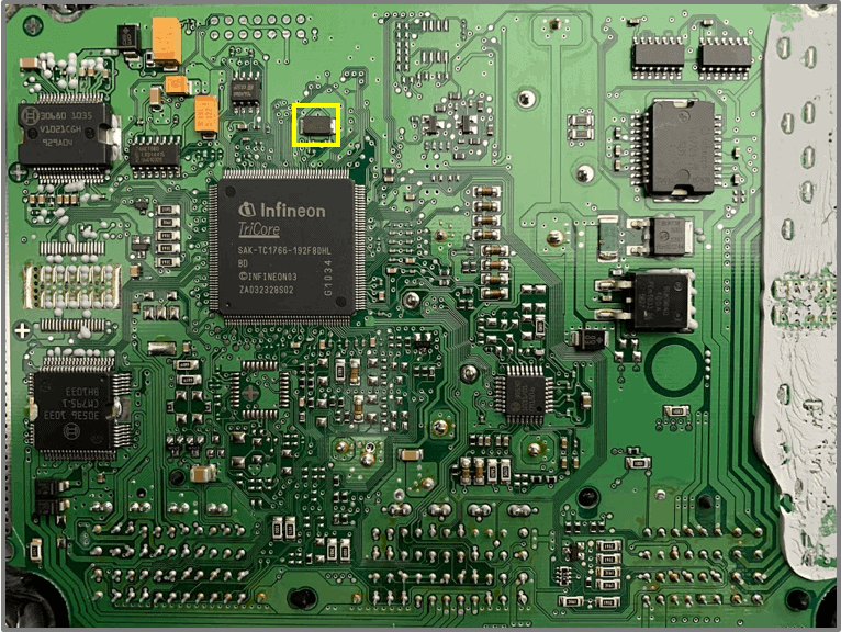
Clock
- Clock 20.000 kHz = 20 Mhz for EEPROM
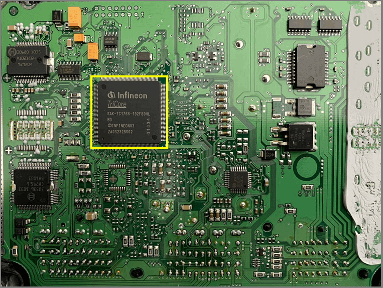
Processor
- All memories are in the processor
- 32 bit Tricore 80MHz
- 56Kb local data SRAM (LMB)
- 1504 Kbyte Program Flash
- 16Kbute boot ROM
- 64 bit bus to LMD
- 32 analog inputs for ADC
- 81 digital I/O lines
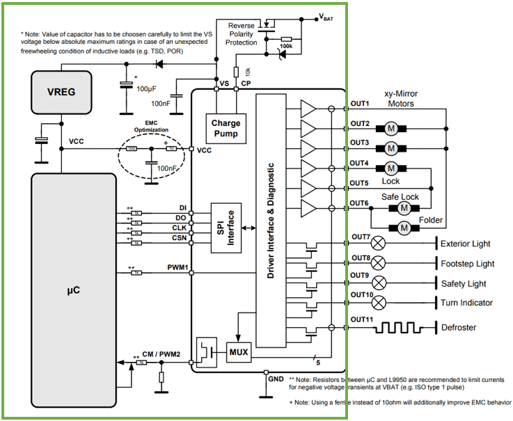
output
- Signals from ECU to the actuators
– via driver ICs
– transistor. Advantage: large flows possible. Disadvantage: current controlled.
– FET transistor. Advantage: voltage controlled. Disadvantage: low currents.
– IGBT (Insulated Gate Bipolar Transistor). Advantages of transistor and FET, so both large currents possible and voltage controlled.