Subjects:
- Drive shaft
- CV joint
- tripod coupler
drive shaft:
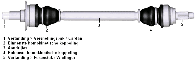
A drive shaft transfers the driving forces to the wheels. On front-wheel drive cars, the drive shaft is mounted with the inside to the gearbox and the outside to the knuckle piece. In the picture below at number 5, the axle protrudes through the wheel bearing, which also has teeth. The teeth mesh together, causing the wheel bearing to rotate with the flange when the drive shaft is driven.
In rear-wheel drive cars, the gearbox is usually longitudinally attached to the engine and the cardan is driven via the cardan shaft, which distributes the power to both drive shafts, so that the rear wheels are driven. Here too, the teeth (fig. number 5) are mounted in the wheel bearing.
Sections 1 and 5 in the image remain horizontal. Because the wheel must be able to spring in and out and make steering movements, there must be moving parts in the drive shaft. These movements are made possible by applying the constant velocity joints. One side of the drive shaft is attached to the gearbox or cardan with a CV joint, the other side with a CV joint in the unsprung part of the strut.
The unsprung means that the part is under the spring and thus follows the road (potholes / hills). The suspended part of the car is everything that rests on the springs (and therefore springs along with the car's compression and extension). So there is a spring in and out and a difference in height with respect to the engine/gearbox and the knuckle piece that contains the axle. It is therefore not possible to mount a complete straight shaft. The shaft will always have to make a certain angle on both sides. When the car is fully compressed, the drive shaft (section 3) will be more inclined than when the car is fully extended.
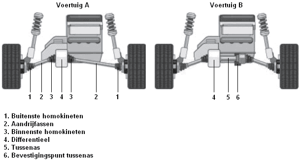
Because a long drive shaft can be disadvantageous for the construction of the car, an intermediate shaft can also be mounted. This is clarified in the image.
With an undercarriage where a drive shaft from vehicle A does not fit; the subframe or wishbone is in the way; then you can choose to mount an intermediate shaft. The intermediate shaft, as seen in vehicle B, is mounted horizontally in the differential. The inner CV-joint of the drive shaft is mounted on the right side of the intermediate shaft. At this point, the drive shaft is attached to a fixed point on the body or subframe.
As a result, the drive shaft on the right-hand side will be at a greater angle than with vehicle A.
CV joint:
A CV joint is also called a Rzeppa coupling (named after the inventor Alfred Hans Rzeppa). A CV joint allows the wheels to be driven while the vehicle can bounce and steer. The coupling is constructed in such a way that the angle at which the drive shaft is positioned does not affect the angular speed at which the shaft rotates. The speed of the inner CV-joint is exactly the same as that of the outer. This is different with a universal joint; this creates an uneven movement.
The image below shows a CV joint applied on the wheel side. The drive shaft can be seen at the bottom left. Furthermore, the ball bearings and the keyways are visible, because the CV-joint here is placed at an angle.

The CV joint is covered by a protective cover as shown in the top image. This cover contains special molykote grease. This cover is very flexible, but will sometimes tear so that the grease can come out. It is important to replace a torn CV joint / drive shaft cover as soon as possible, because the grease disappears and sand etc. can get in. Sand and dirt will stick to the grease. As a result, the CV-kinetic coupling will quickly break. When a CV joint is defective, a ticking sound will be heard on the wheel side when cornering and a vibration will be caused on the gearbox side during acceleration.
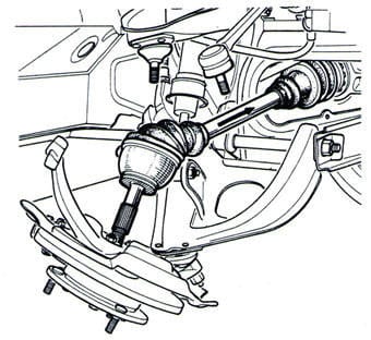
When replacing the dust cover, the drive shaft must be disassembled. Sometimes it is possible to replace the cover while the drive shaft is still mounted on the final deceleration (gearbox or differential). The stub axle must be loosened at the top or bottom. Often the outer tie rod of the track rod must also be removed from the knuckle. This can be seen in the image.
When the drive shaft has been removed from the stub axle, the hose clamp must first be loosened from the cover. The cover can be slid off the CV joint, after which the CV joint can be disassembled from the drive shaft. Often the CV joint can be knocked off with a hammer; the retaining ring is on the drive shaft, in the CV joint. Sometimes there is also a retaining ring on the drive shaft that must first be disassembled before the CV joint can be slid off. Please refer to the manufacturer's repair manuals for this.
When mounting the CV joint, make sure that the retaining ring is in place; when the circlip is on the drive shaft and the CV-joint must be slid over it, the CV-joint must be slid far enough on the shaft. If not, the CV-joint will slip off the axle during steering movements. To check that the CV-joint and circlip are properly in place, play can be felt on both parts; there should be a very small play. If the CV-joint is completely fixed on the axle, there is a possibility that it is not yet properly in place.
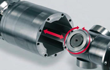
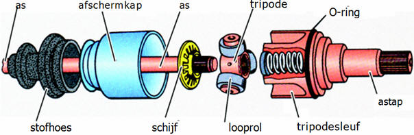
Tripod coupler:
A tripod clutch is often used on the inside (gearbox or differential side). This is not always the case; the CV-joint described above is also often used. A tripod coupling works differently and can be recognized by its larger housing. The tripod coupling is shown in the image below.
The tripod coupling often has three revolving rollers that are slid into a slot in the housing. The track rollers enable the drive shaft to make a pure rotating movement, just like with the Rzeppa coupling. The advantage of this coupling is that the drive shaft can move back and forth over a large distance in the housing. This clutch is susceptible to vibration when worn. The keyways in the housing will deform, forcing the rollers to move differently than intended, resulting in vibration. This vibration can be felt in the steering wheel during acceleration and sometimes in the entire car. By dismantling the drive shaft, it is very easy to determine whether the tripod coupling is worn, or whether the cause must be sought elsewhere. After removing the grease, one can feel for any discrepancies in the housing by hand; if you can feel a dimple or a burr, it is recommended to install a new coupling.
Sometimes only one of the two tripod couplings is defective. Since the price of these couplings is very high, it is worth checking in advance which coupling is actually worn before both sides are replaced preventively.
The image below shows an exploded view of a tripod coupling.
Related page: