Subjects:
- Preface
- Overview of the HV system
- Converter operation
- Boost converter
Preface:
We find converters in hybrid and fully electric vehicles. The converter converts a high DC voltage into a low DC voltage. We therefore call this component a DC-DC converter. The high voltage from the HV battery of 200 to 600 volts (depending on the vehicle) is converted in the converter into 14 volts DC for the on-board battery. The electrical components in the interior and exterior (such as lighting, radio, door locks, electric window motors, etc.). are supplied with voltage and current by this battery.
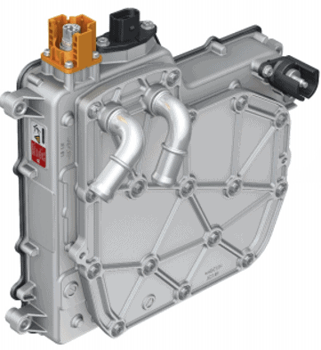
The converter is built into the vehicle as its own high-voltage component. The connection for the high-voltage cable can be recognized by the orange plastic cap.
The converter contains two coils with a soft iron core in between. A high current flows through the coils. Because of the heat development, the converter is connected to the cooling system. The circulating coolant absorbs the heat and transfers it to the radiator.
Overview of the HV system:
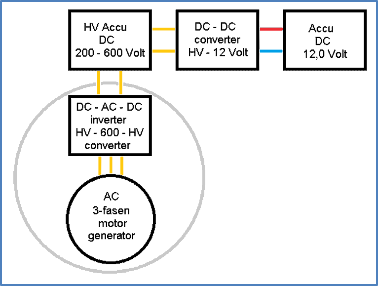
The high voltage from the HV battery is sent to the via high voltage cables reverse conducts. The conversion from DC to AC takes place in the inverter (the voltage inverts from direct voltage to alternating voltage). The HV electric motor (synchronous or asynchronous) is set in motion with this alternating voltage.
The HV battery also powers the DC-DCconverter which converts the high voltage to an on-board voltage of 12 to 14 volts.
The following figure shows the components of the HV system schematically.
Operation of the converter:
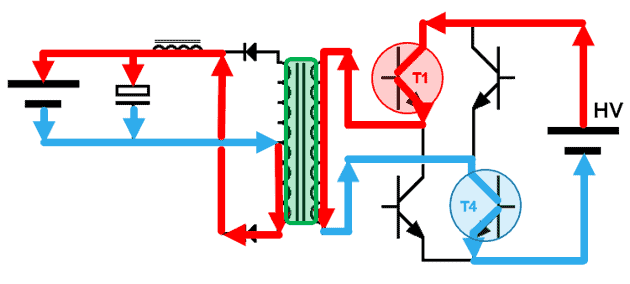
The converter is mounted between the HV battery and the 12-volt on-board battery. The following figure shows the components from left to right:
- 12 volt on-board battery;
- capacitor (elco);
- suppressor coil (to filter high-frequency peaks);
- diodes (rectifiers);
- transformer with galvanically isolated coils;
- H-bridge with four transistors;
- HV battery
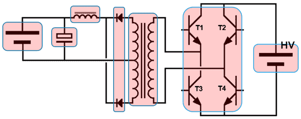
The transfer of high voltage to 14 volts takes place by means of induction of coils. The connection between the low and high voltage system is galvanically isolated: that means there is no conductive connection between the two systems.
De incoming coil (N2, HV side) provides an alternating magnetic field in the soft iron core. The outbound coil (N1, 14-volt side) is in an alternating magnetic field. This is where tension is generated.
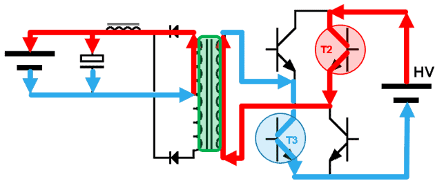
The HV system ECU turns the transistors T2 and T3 on (see the following figure). With this transistor T2 connects the plus of the HV battery to the underside of the primary coil. The current leaves the top via the coil and flows back to the negative of the HV battery via transistor T3.
The primary current creates a magnetic field in the transformer, which generates a voltage in the secondary coil. The generated magnetic field and thus also the voltage are lower in the secondary coil than in the primary coil. The left battery and capacitor are charged with a DC voltage of around 14,4 volts.
The transformer only works with alternating voltages. Because batteries only supply a DC voltage, an alternating magnetic field takes place by switching transistors on and off.
For this reason, the transistors T2 and T3 switch off, after which T1 and T4 switch on immediately. Current in the primary coil now flows in the opposite direction (from top to bottom). As a result, an opposite magnetic field is generated in the transformer and thus also an opposite voltage in the secondary coil. In this situation, too, the charging voltage of the battery and capacitor is around 14,4 volts.
Example:
- AC in: 201,6 volts;
- N1: 210 turns, R = 27,095 ;
- N2: 15 turns, R = 0,138 ;
- Winding ratio (i) = N1 : N2 = 210:15 = 14;
- AC out = AC in : i = 201,6 : 14 = 14,4 volts;
- P in = U^2 : R = 201,6^2 : 27,095 = 1500 Watts;
- P out (lossless) = U^2 : R = 14,4 : 0,138 = 1500 Watts;
- Efficiency = 90%;
- P out (actual) = P out * efficiency = 1500 * 0,9 = 1350 Watts;
- Battery current (I) = P : U = 1350 : 14,4 = 93,75 Ampere.
Boost converter:
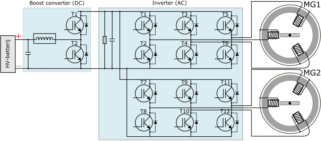
The image below shows a system overview including the boost converter and the reverse of a Toyota Prius.
The battery voltage of 201,6 volts is converted in the boost converter into a DC voltage of 650 volts. A coil and two IGBTs (transistors) are used to generate an induction voltage. The reactor coil is shown in the boost converter between the capacitor (left) and the IGBTs T1 and T2. By continuously driving the transistors or not, an induction voltage is generated in the reactor coil, causing the capacitor to charge.
The diode ensures that the charging voltage continues to increase until the voltage reaches 650 volts.
Related pages:
- Electric drive (Overview);
- HV battery;
- Inverter.