Subjects:
- Hydraulic control slide
Hydraulic control slide:
The hydraulic control valve, also called a control valve, has the task of controlling the flow direction of hydraulic oil. The control slide can be operated manually or electrically.
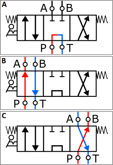
The following three images show the control slide symbol in three different positions:
- A: The control slide is in the middle position. The hydraulic fluid from the pump is fed directly to the return;
- B and C: The hydraulic fluid is fed to the cylinder. The difference between B and C is that they are cross links to each other. This makes it possible to reverse the direction of movement of the cylinder. More on this later.
The control slide shown is a 4/3 slide, which means that it has four connections (A, B, P and T) and three positions (center, left and right).
The control slide often has a central position, which in that case can be seen by the springs on both sides. The springs push the control slide back into the center position as soon as it is no longer actuated.
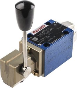
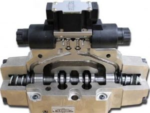
The three images below show a manual control slide (left) and an exploded control slide (center) and an animation of the control (right). An explanation of the operation follows in the section below the images.
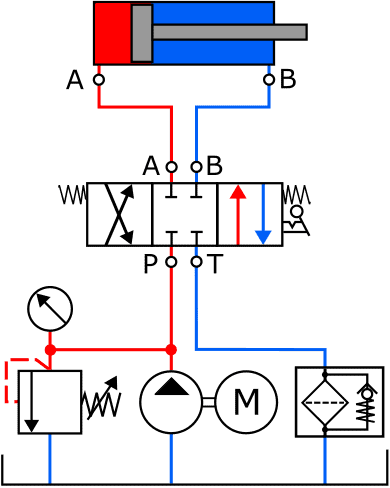
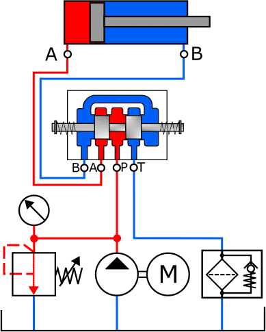
As mentioned before, the 4/3 control slide can be set in three positions. The two images below show the control slide in the middle position. The piston is not actuated. On the left is the standardized control valve symbol in the diagram, on the right the actual fluid circuit created in this position. The gaps between B, A, P and T are closed by the plungers.
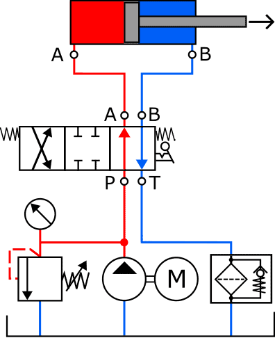
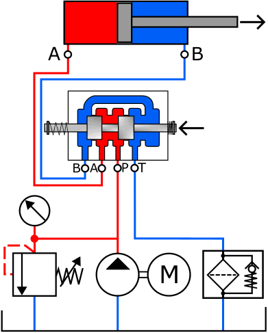
The fluid openings change when the control valve is operated. In this case, the pump pressure is allowed on the left side of the piston (A). The oil on the right side flows through connections B and T, through the filter, back to the reservoir. The actual fluid circuit image clearly shows that the control slide has been pushed to the left, opening the gap between A and P (red) and B and T (blue) to allow the hydraulic fluid to flow through.
- The hydraulic fluid enters through port P and exits the control valve through port A to make its way to the cylinder;
- The return channel is also released: the liquid can flow to the reservoir via connections B and T.
Related page: