Subjects:
- Preface
- Read fault memory
- Look up electrical diagram
- Multimeter measuring
- Why we measure a voltage of 5,7 volts
Preface:
With a case we deal with a real malfunction that can be found in practice. In order to be able to search for faults, one must have the knowledge and skills to operate reading equipment, consult electrical diagrams, measure with measuring equipment and assess measurement results. Therefore, first study the following pages:
- OBD diagnosis;
- Reading electrical diagrams;
- Sensor types and signals (passive, active and intelligent);
- Troubleshooting the sensor wiring;
- Measuring with the multimeter en oscilloscope.
Read out fault memory:
In this case we treat a car with a loss of power. The engine fault light is on.
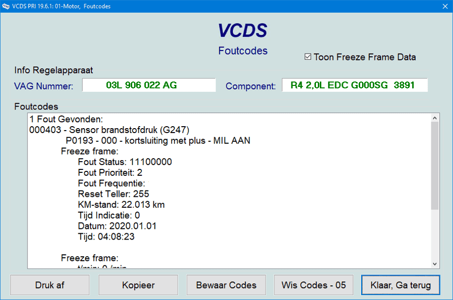
In the event of a complaint from the customer and/or burning malfunction lights, we first read out the car. The following fault is active:
P0193 - fuel pressure sensor G247 - short circuit to plus.
The fault reappears immediately after deletion. So he is permanently present.
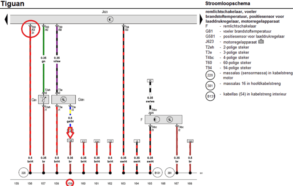
Look up electrical diagram:
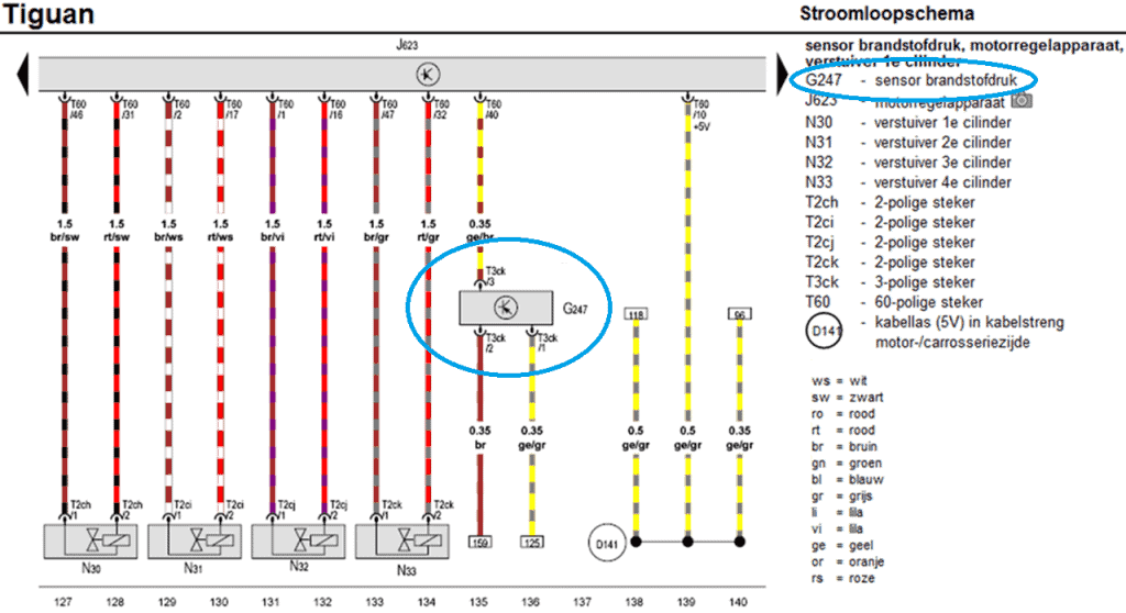
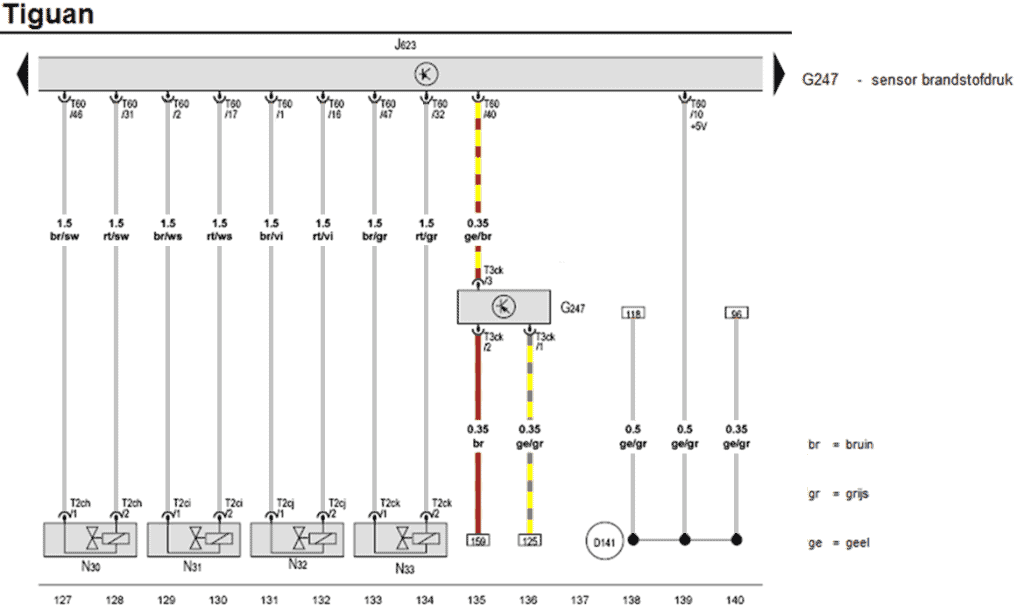
We look up the fuel pressure sensor with the component code G247 in the electrical schematic. The sensor has a three-pin plug (T3ck). The yellow/brown wire (pin 3 of the sensor) is connected to pin 40 on the engine-ECU (J623). This is the signal wire. The other two wires (pins 1 and 2) go through references 159 and 125 to other coordinates in the schematic.
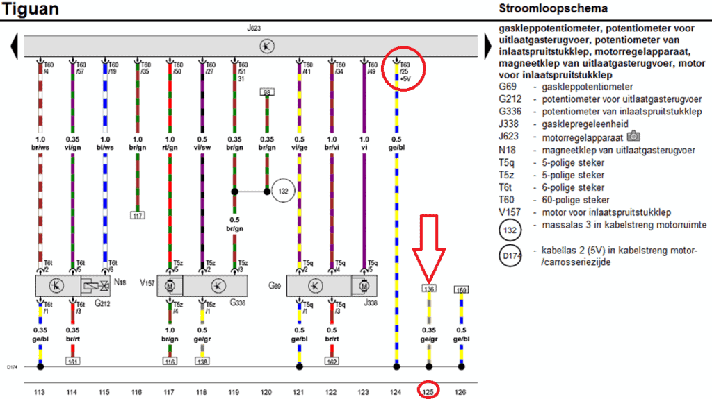
We look for coordinate 125 to follow the yellow/grey wire. In the following diagram we see that the yellow/grey wire is connected to node D174 (cable splice 5 volts) which is connected to multiple components. The cable weld ends with the yellow/blue wire at the ECU on pin 25. This is the power wire for the fuel pressure sensor, among other things.
Let's go back to the fuel pressure sensor schematic again. We know that pin 1 is connected to the common plus terminal for the sensors.
We now follow the reference 159 and end up in the following scheme. The brown wire leads to a ground weld and is connected to pin 53 of the ECU.
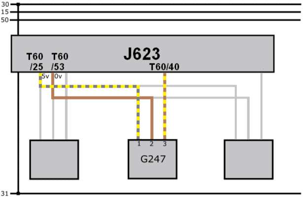
We return to the original scheme and focus on the fuel pressure sensor. We make the wires that we do not use gray in color.
The original electrical diagram contains references: this can lead to confusion. For that reason, we make a simplified scheme. This shows the joint power supply and ground (pins 25 and 53) and the signal wire (40).
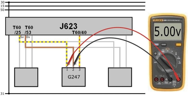
Measuring with the multimeter:
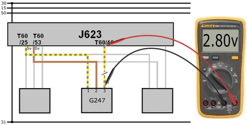
With the voltmeter we measure the supply voltage in relation to the ground. The multimeter shows 5.00 volts in the display: this tells us that both the plus and ground wires are OK.
The signal voltage (measured relative to ground) is 2,9 volts. This value is real: on the basis of this voltage we cannot conclude that there is a short circuit with plus.
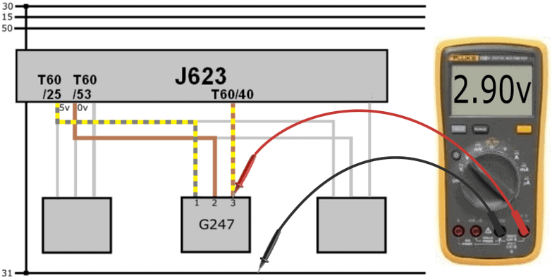
The signal voltage of 2,9 volts from the sensor is sent to the ECU. Yet we measure a voltage of 5,7 volts on the ECU.
The voltage on the ECU side is higher than the voltage output from the sensor.
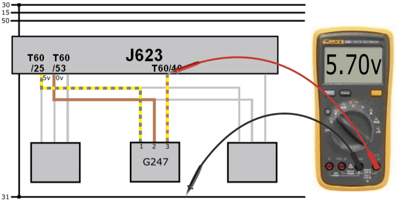
When there is a difference in voltage across a wire, there may be a transition resistance. However, the voltage on the sensor side should be higher; now the tension on the “receiving” side is higher.
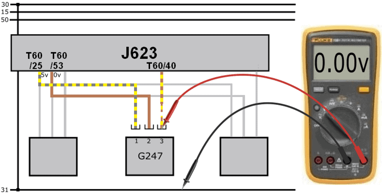
The plug is removed from the sensor. When measuring in the plug we measure 0 volts.
The voltage difference of 2,8 volts can be explained:
- On pin 40 of the ECU we measure a voltage of 5,7 volts because of the internal circuit;
- The sensor transmits a voltage of 2,9 volts;
- The voltage difference between the sensor and ECU is: (5,7 – 2,9) 2,8 volts.
- With the plug removed we measure 0 volts in the plug, but still the 5,7 volts on the ECU side.
- Conclusion: the signal wire is interrupted.
The wire break was in a portion of the wiring harness that was not attached to a fixed point. The wiring harness holder broke off during a previous disassembly. The wiring harness has been able to move for quite some time. Eventually the signal wire is worn through. After repairing the signal wire and some other slightly damaged wires, the harness holder was reattached properly and the error cleared up.
Why we measure a voltage of 5,7 volts:
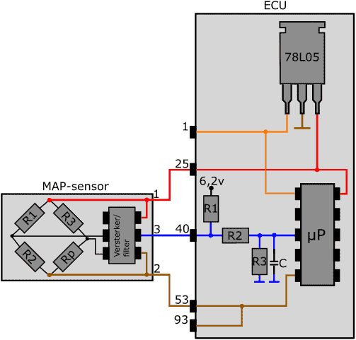
The following image shows the circuitry in the ECU. The signal from the active MAP sensor is sent to pin 40 of the ECU via the blue wire. Inside the ECU are a number of resistors (R1, R2, R3) and a capacitor (C). The signal wire from the sensor is connected between resistors R1 and R2 in the ECU.
The sensor cannot send information to the ECU in the following situations:
- the sensor plug has been disconnected;
- the plus, ground or signal wire is interrupted;
- the sensor is defective (internal interruption).
In these situations, therefore, no current flows from the sensor to the ECU. However, a current circuit in the ECU is active: current flows through R1, R2 and R3.
We are dealing with a voltage divider: there are three resistors in series. The microprocessor measures the voltage between R2 and R3. The supply voltage of the first resistor is 6,2 volts. The three resistors each absorb a part of this voltage. After the last resistance we see a mass symbol. At that point, the voltage is (obviously) 0 volts.
When the signal wire is interrupted, the first resistor takes up a voltage of 500 mV. So between resistor R1 and R2 we measure a voltage of: (6,2 – 0,5) = 5,7 volts. For this reason, in the case where the sensor does not provide any information, we measure the voltage of 5,7 volts on pin 40 of the ECU.
Thanks to ACtronics for providing the info about the circuitry in the ECU.