Subjects:
- Introduction
- Different carburetor types
- Main body
- Cold start
- Stationary and transfer section
- Acceleration
- Full load
Introduction:
Until the early 90s, car manufacturers produced new petrol engines where the fuel supply was controlled by a venturi carburettor. The carburetor is located on the engine's intake manifold. The fuel and air are supplied and mixed in the carburettor.
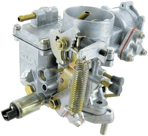
The picture shows a carburettor of the brand Solex which was used on the VW Beetle. Other well-known carburettor brands are: Zenith, Stromberg, Weber, Rochester, Holley, Binks, Carter and SU
Engines equipped with a carburettor could no longer meet the requirements with effect from the latest emission standards (Euro 1). The carburettor has since been replaced by the computerized engine management system, which is still under development.
Because new cars have not been fitted with a carburetor for almost three decades, this subject is often no longer included in the teaching material of current car technology courses.
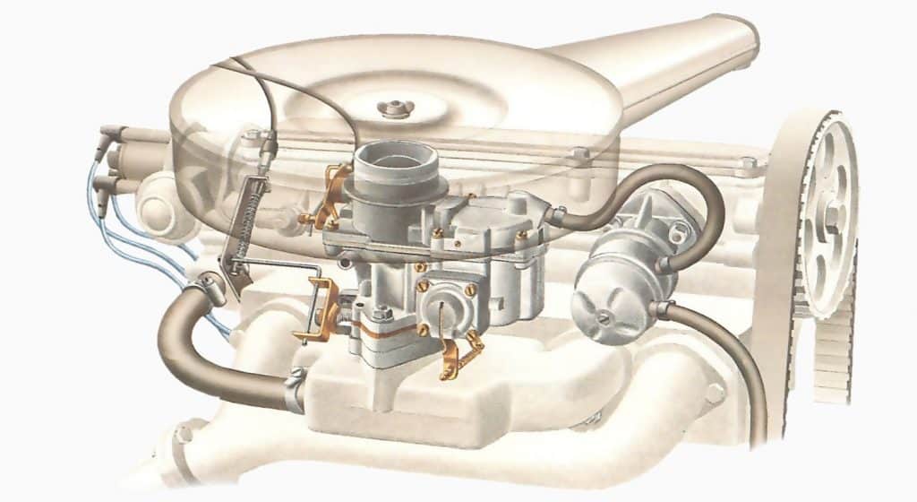
The carburetor is positioned between the intake manifold and the air filter. The image below shows the position of the carburettor on the engine.
Different carburetor types:
The way the carburettor is mounted on the engine affects the flow direction. The figure below shows the downdraft (left), updraft (center), and flat flow carburetor (right).
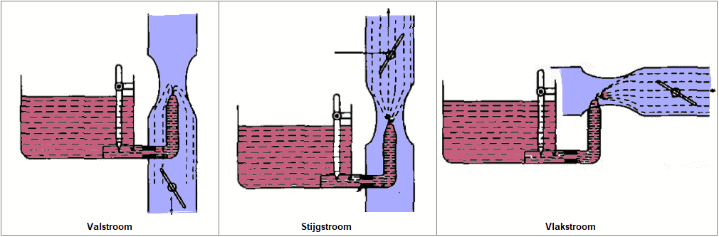
- Downdraft: The air enters at the top and flows down. The fuel flows with the air direction and with the help of gravity to the cylinders. This type is the most commonly used.
- Updraft: The airflow is in an upward direction. The weight of the fuel results in a less easy flow than with the downdraft carburetor. This type has not been used in recent years in the carburettor era.
- Plane flow: is in a horizontal direction.
Main body:
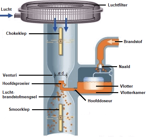
A mechanical fuel pump supplies fuel to the float chamber of the carburetor. Due to the rising fuel level and the floating float element, the supply line is closed with the needle. The needle opens the supply as soon as the fuel level drops. From the float chamber, the fuel flows through the main doser into the main jet. The fuel level in the main jet is kept below the jet opening by the level in the float chamber. In the event that the needle does not close properly (due to a defect or contamination), the fuel level in the float chamber becomes too high and too much fuel flows through the main jet to the engine.
The throttle/throttle valve is connected to the accelerator pedal. The opening angle of the throttle influences the negative pressure and air speed in the venturi (narrowing in the suction tube). DThe amount of petrol that is drawn out of the main jet depends on this underpressure. BWith an increasing air speed, a higher negative pressure is created, so that more gasoline is added to the air. The optimum fuel/air ratio depends on the size of the main metering unit in relation to the diameter of the venturi. The size of the main metering unit is suitable for a very limited speed range. The mixture quantity determines the engine torque.
The relationship between the increasing air speed and the associated underpressure and the outflow of the gasoline can result in mixture enrichment occurring and continuing to increase. The nozzle with brake air regulation compensates for this. Mechanically, the brake air system tries to keep the air-fuel ratio stoichiometric. The holes in the brake air tube(s) should prevent enrichment and keep mixture stoichiometric. The brake air holes have different diameters.
- Low speed: negative pressure is relatively low, petrol flows from the main metering unit out of the main body.
- Higher speed: negative pressure rises, more petrol is sucked in than the main metering unit can deliver and therefore limits the petrol flow. The level in the mixing tube(s) drops, releasing the first air holes in the mixing tube. The air from the air dispenser is mixed with the gasoline.
Due to the supplied air, the negative pressure drops and the petrol flow slows down. The higher the speed, the more air gaps are released and the more brake air is mixed with gasoline. At very high speeds it can happen that the tube is completely empty and air is drawn in from the stationary part.
Cold start:
To get a sufficiently rich mixture during the start we see two versions:
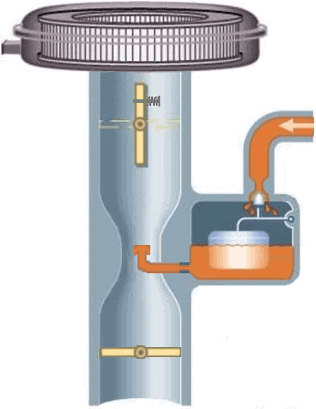
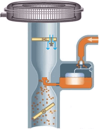
Version with choke valve:
The explanation refers to the two images below. The choke valve is located at the top of the carburetor. The choke valve has a hole that is closed at rest with a spring-loaded valve. When starting a (cold) engine, you can manually close the choke valve. The negative pressure “sucks” the valve open so that air can be drawn in. Due to the small air gap, a large vacuum is created on the main body during starting so that gasoline is also drawn in. However, the throttle valve must be partially open, otherwise there will be no vacuum at the main jet. A linkage between the two valves allows both valves to be operated simultaneously, without having to operate the accelerator pedal. After the engine has started, the choke can be opened again. At a warm outside temperature this can be done sooner than at temperatures around the freezing point.
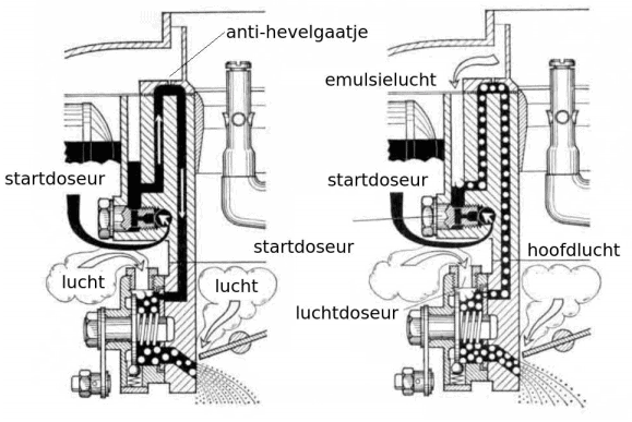
Version with starter carburettor:
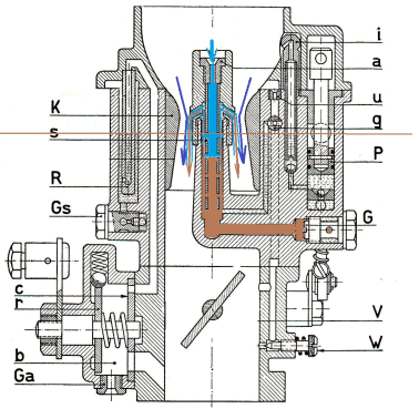
The starter carburettor does not use a choke valve but has a separate fuel supply section. The image below shows a carburettor of this type.
The throttle valve should be closed for a cold start. The moment the driver operates the choke knob, a slide in the carburetor rotates and openings connect to the starter portion of the carburetor. The petrol is drawn in from the starter metering unit and mixed with the incoming air in the air metering unit. The vacuum under the throttle sucks the air/fuel mixture in. In this situation, the throttle is still closed. After the engine has started, the higher vacuum drains the petrol tube from the starter metering unit. The emulsion air provides extra air to prevent a mixture that is too rich.
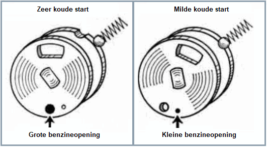
The operating slide can be designed with two through-flow openings of different diameters. The driver can then choose between a very cold start, a mild cold start and warming up the engine.
Stationary and takeover section:
During idling, the throttle valve is closed and there is a high underpressure under this throttle valve. Due to the low airflow, there is too little underpressure in the venturi to suck petrol out of the nozzle. There is a high negative pressure under the throttle. In this situation, an additional fuel channel under the throttle provides the engine with the correct amount of petrol. The picture is of a Solex carburetor.
The adjusting screw to adjust the amount of mixture affects the CO value. The idle speed should be adjusted with the adjusting screw on the throttle valve.
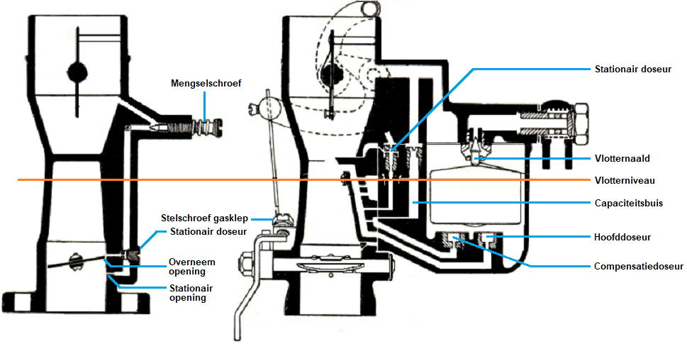
The image below shows the idle (left) and main (right) body of a Zenith carburetor. The Zenith has many similarities with the Solex carburetor described earlier.
The idle opening is located below the throttle and the transfer opening is just above the throttle. The moment the driver starts to accelerate, the transfer section supplies extra fuel. After that, the main part takes over. The main body also provides fuel for idling. The fuel passes through the stationary metering unit and the adjustable mixing screw. A second stationary metering unit is mounted near the gas valve. The speed should be adjusted with the throttle adjusting screw. The main dispenser and counter dispenser are both mounted at the bottom of the float chamber and form the main body. The capacity canister serves as a storage chamber and is filled with fuel.
Acceleration:
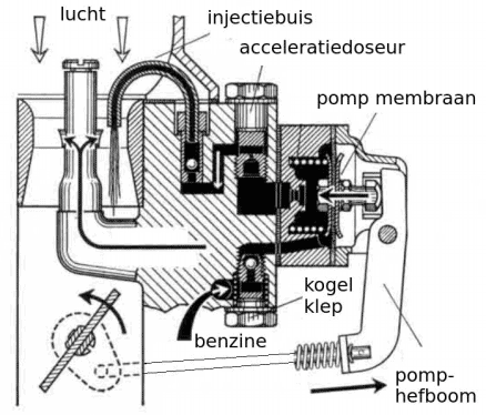
A Solex carburetor is equipped with a mechanically or pneumatically operated accelerator pump. When pressing the accelerator quickly, a richer mixture is needed for a good mix ratio and more power. The spring is tensioned and moves the pump diaphragm to the left. The gasoline is injected into the venturi through the diaphragm and the accelerator meter and the injection tube.
The ball valves ensure the suction and discharge of the petrol and are dependent on the spring force. The tension can be adjusted manually.
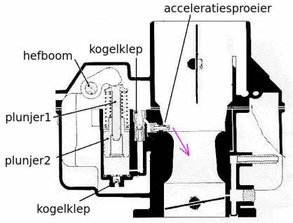
The following image shows the mechanically actuated acceleration section of a Zenith carburetor. The inner plunger is pushed down when the accelerator pedal is depressed. The fuel injection takes place via the accelerator nozzle. The spring of the outer plunger is tensioned, so that the injection time depends on the – gradually relaxing – spring tension. Not the position of the lever, but the spring tension determines the injection time. Two ball valves ensure – just like with the Solex carburetor – the suction and discharge of the petrol.
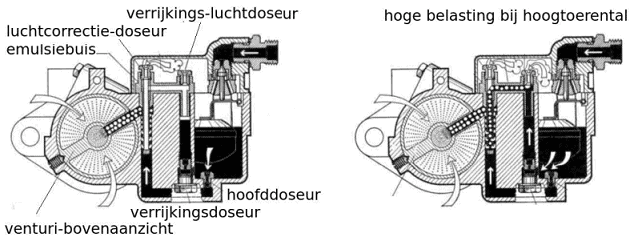
full load:
The mixture should also be enriched at full load and higher speeds. The carburetor may be equipped with a separate enrichment section that is part of the main body. During partial load, only the main body provides fuel. A higher load and higher speeds cause more negative pressure in the venturi. Due to this negative pressure, additional fuel is drawn in via the enrichment dispenser (see illustration).