Subjects:
- Preface
- Drive-by-wire
- Combination of electric and hydraulic braking
- Brake blending
Preface:
Vehicles with electrified propulsion (hybrid, full EV, fuel cell) have the option of electrical braking. When the accelerator pedal is released, or with light braking, the electric motor works as a generator. The kinetic energy of the vehicle is converted into electrical energy for the HV battery. The range rises when braking is much more gentle and the braking system has the opportunity to apply a lot of regenerative braking. You can read more about this on the page: inverter.
In 2023, electric braking is still in combination with the conventional hydraulic braking circuit. In the event of an electrical fault, or in the case of an emergency stop in older vehicles, the hydraulic braking circuit is (partially) activated. This serves as a backup. The following paragraphs show how manufacturers combine electric and hydraulic braking to ensure good comfort and safety in the event of an electrical system failure.
Drive-by-wire:
The purpose of the “drive by wire” braking system is to brake hydraulically with electric assistance. There is no direct hydraulic connection between the brake pedal and the brake pistons in the calipers. With the brake pedal, braking pressure is applied to a so-called brake force simulator. The brake pressure is measured. An electric motor builds up the desired pressure in the hydraulic brake circuit. The drive by wire braking system offers the following advantages over the conventional braking system:
- A vacuum brake booster is no longer used, as the electric motor provides the necessary fluid pressure;
- Fluid leakage can be recognized and closed per brake. For this reason, a master brake cylinder is no longer required for two separate brake circuits;
- The driver does not notice a transition between electric and hydraulic braking when switching from regenerative braking on the electric motors to braking by pressing the brake pad against the disc;
- Vibrations from the ABS system are no longer felt in the brake pedal;
- The (simulated) back pressure in the brake pedal can be adjusted to the settings (comfort / sport).
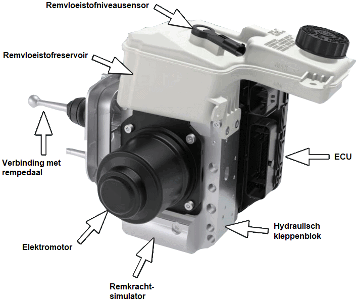
The hydraulic diagram below shows the system used by BMW (DSCi). The operation is as follows:
The moment the driver operates the brake pedal, force is exerted on the master brake cylinder (7). This brake master cylinder has two outputs: to the brake pedal force simulator (8) and to a release valve. The simulation pressure is transmitted to the brake pedal force simulator via the blue line. In this component a counter pressure is created, which is recognizable by the driver as counter pressure in the brake cylinders. There is no physical connection from brake master cylinder to wheel brake cylinders. The simulating pressure is measured by a pressure sensor (5). Depending on the simulation pressure, the ECU controls the electric motor (10). This exerts a working pressure in the brake pressure cylinder (9). A pressure sensor in the working pressure side feeds the built-up pressure back to the ECU. The red connections in the diagram show how the working pressure reaches the wheel brake cylinders (1) via the valves. The pressure loading valves (3) are open when at rest, so that the brake pressure can be built up directly from the brake pressure cylinder. The pressure reducing valves (2) are closed at rest.

Description:
- Remmen
- Pressure reducing valves
- Pressure holding valves
- Decoupling valves
- Pressure gauges for brake pressure working circuit and simulator circuit
- Brake fluid reservoir
- Master cylinder
- Brake Pedal Force Simulator
- Brake pressure cylinder
- Electric motor
- Diagnostic valve
- Yellow connections: supply and return brake fluid reservoir;
- Blue connections: simulation pressure;
- Red connections: working pressure (brake pressure).
In the event of a leak near the brake pressure cylinder, or an electrical fault that prevents the electric motor from building up sufficient working pressure, the release valves (4) are energized to guarantee safety. The connection between the master brake cylinder and the wheel brake cylinders is opened and the connection to the brake pressure cylinder is closed. Because the brake booster is missing, you have to push the brake pedal more forcefully in order to brake.
Combination of electric and hydraulic braking:
Fully electric and hybrid vehicles always have a combination of an electric and hydraulic braking system. The “brake by wire” braking system of the previous paragraph is not often used yet. In that system there is no direct connection between the brake pedal and the wheel brake cylinders. A strong electric motor provides all braking power, even during an emergency stop. In that case, a brake booster is not necessary.
In most electric and hybrid vehicles, a combination of electric and hydraulic braking is achieved as follows: with soft (dosed) braking, regenerative (electric) braking takes place because the electric motors function as a dynamo. In the event of hard braking and / or in the event of malfunctions, the hydraulic system switches on immediately. Here a brake booster is used to amplify the brake pressure. During braking, therefore, there is an interaction between the electric motor and the mechanical brakes. This system is sometimes also referred to as “drive by wire”, although this term lends itself better to the system from the previous section.
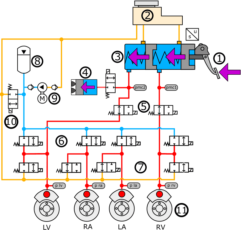
The diagram below is based on the Toyota Prius 3. Brake pressure is built up in the master cylinder (1) with the brake pedal (3). With soft braking, braking is only applied to the electric motors. The brake pressure simulator (4) creates counter pressure when the brake pedal is pressed. The valve for the brake pressure simulator opens in normal operating condition. Under hard braking, the locking valves (5) are opened and the simulator door is closed. The brake calipers of the front wheels are supplied with braking pressure. Opening and closing the hydraulic valves (6) allows the brake pressure to also reach the rear wheels. The brake pressure sensors (from left to right: p lv to mp rv) measure the pressure and transmit it to the ECU. The hydraulic valves (5, 6 and 7) are regulated by means of a PWM signal based on the desired brake pressure.
The system is designed in such a way that, in the event of a power failure, the brake pressure on the rear wheels is completely discharged and the pressure on the front wheels is regulated by the driver with the brake pedal.
Description:
- Brake pedal
- Brake fluid reservoir
- Tandem master cylinder
- Brake pressure simulator
- Locking flaps
- Hydraulic valves (left to right closed)
- Hydraulic valves, front closed, rear open
- Pressure accumulator
- Hydropump driven by electric motor
- Pressure limiting valve
- Yellow connections: supply and return brake fluid reservoir;
- Blue connections: brake pressure from hydraulic pump;
- Red connections: brake pressure from master cylinder (with valves open).
The hydraulic braking of the Toyota Prius 3 is done via the front wheels. The rear wheels are not connected to the brake master cylinder. This is the case with modern vehicles, including the Kia Niro: all four brake cylinders are energized by means of two circuits from the master brake cylinder.
When braking vehicles with a similar braking system, a switchover from electric to hydraulic braking takes place under certain circumstances. In order to make the braking deceleration and the feeling in the brake pedal run smoothly, this braking system uses "brake blending". This is described in the next section.
Brake Blending:
When the accelerator pedal is released or the brakes are dosed, many electric vehicles only brake using the electric motors. The kinetic energy is converted into electrical energy, which increases the range of the vehicle. The hydraulic braking system is barely used. When a large braking deceleration is required, the electric brake and the hydraulic service brake work together. We call the cooperation of the two braking systems “brake blending”. In previous generations of hybrid and fully electric vehicles, this did not go smoothly and the vehicle's deceleration changed during the hydraulic brake application. With current technology, the driver no longer notices the transition between the two braking systems. Note: this is not the technique used with drive by wire.
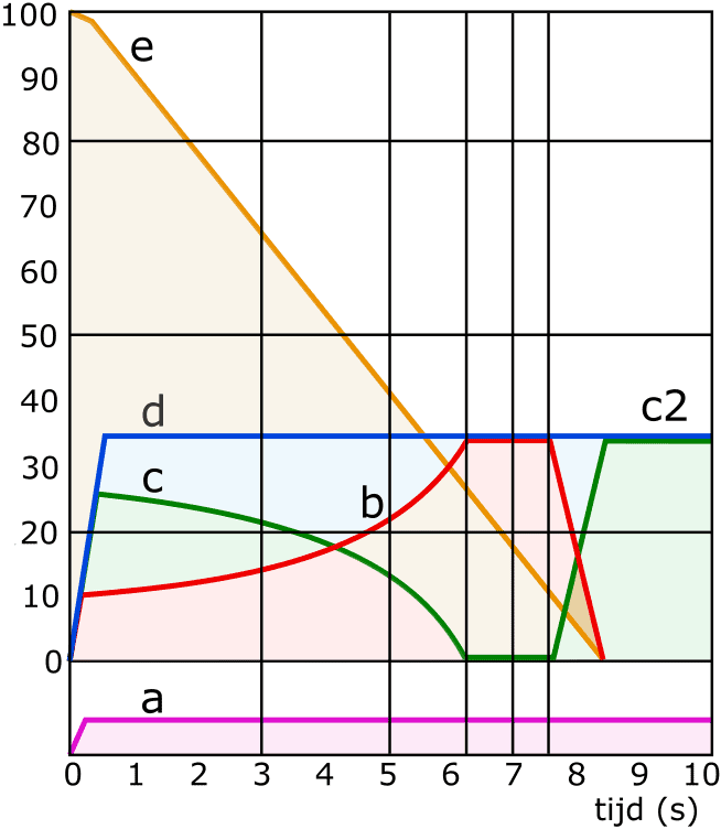
The graph shows the transition of the two braking systems with the braking deceleration remaining constant. The driver's pedal force (a) remains the same for 10 seconds. When braking is initiated, the hydraulic service brake and regenerative braking on the electric motors work together. The first six seconds we see that the deceleration due to regenerative braking increases. The electric motor functions as a generator and supplies the HV battery with the generated energy. The braking force of the hydraulic service brake continues to decrease until it no longer cooperates. After approx. 7,5 seconds we approach the standstill of the vehicle and the electric braking power is lost. The hydraulic braking force increases again. The vehicle stops after 8,5 seconds. The driver briefly depresses the brake pedal.
a: driver pedal force
b: deceleration by regenerative braking (using electric motor)
c: deceleration by hydraulic service brake
d: delay desired by the driver
e: speed reduction
d = c + b
Related pages: