Subjects:
- Preface
- Vane / Vane Pump
- Reciprocating compressor (reciprocating, crankshaft type)
- Tilt plate compressor introduction
- Fixed Stroke Tilt Plate Compressor
- Variable stroke tilting plate compressor (with internal and external control)
- Lubrication of the compressor
- Magnetic clutch
- Sounds
Preface:
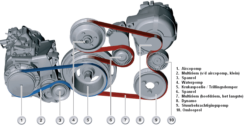
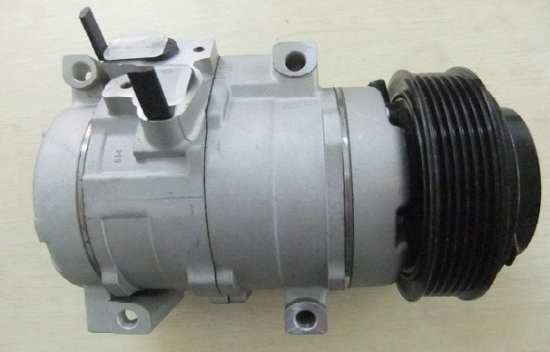
The compressor pumps the refrigerant gaseous refrigerant from the air conditioner throughout the system. The pressure and temperature of the refrigerant increase as it leaves the compressor. There are different types of compressors that can be used for air conditioning. Reciprocating compressors are used in modern automotive air conditioning systems. “Reciprocal” means that the components in the compressor make reciprocating movements. The operation of these compressors can be compared to that of a reciprocating engine. Reciprocal compressors also consist of two types, namely the crankshaft type and the tilting plate compressor. In modern cars, the tilting plate compressors are used, which in turn are divided into two types: the tilting plate compressor with fixed stroke and the variant with variable stroke. The air conditioning pump, just like the alternator and the power steering pump, is driven by the multi-belt in combustion engines (see image below). We find electric air conditioning compressors in hybrid and fully electric vehicles. An electric motor is fed by the HV system and drives the compressor.
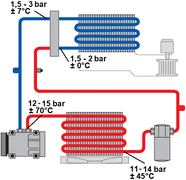
The air conditioning compressor sucks the gaseous refrigerant from the evaporator, which keeps the pressure in the evaporator low and contributes to the evaporation of the refrigerant, even at low temperatures. The compressor compresses the gaseous refrigerant, which leads to the transition from low to high pressure. This increase in pressure and temperature causes the refrigerant to change from gaseous to liquid.
The pressure supplied by the A/C compressor is affected by several factors, including:
- The engine speed (in combustion engines);
- The type and amount of refrigerant;
- The temperature of the refrigerant;
- The type and design of the air conditioning compressor, which determines the capacity;
- The adjustment of the magnetic coupling;
- The ambient temperature.
After compression, the refrigerant leaves the compressor at a temperature of approximately 70 degrees Celsius. This temperature is then lowered in the condenser.
The following paragraphs discuss various versions of air conditioning compressors, which may or may not be used in the automotive industry.
Vane / Vane Pump:
This pump is rarely used in a car air conditioning system. However, it can be used in specific cooling installations for different products.
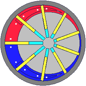
Operation: The (gray) disc rotates to the right, clockwise. The yellow plungers are pressed against the wall by centrifugal force, separating the different chambers. At the bottom right, the refrigerant flows in and follows its way to the small blue room. Due to the rotation, this space becomes larger, which leads to negative pressure. The pump continues to run, causing the refrigerant to enter the red area. Here, the room space gets smaller and smaller, causing the refrigerant to be pressurized (compressed). At the end of the red chamber is the exhaust valve, through which the refrigerant is forced out.
Reciprocating compressor (reciprocating, crankshaft type):
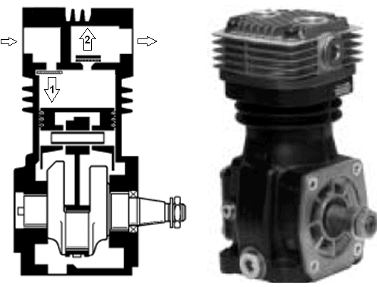
This pump, like the vane/vane pump, is rarely used in a car's air conditioning system. However, it can also be used in specific cooling installations for different products. The image below shows a reciprocating compressor, where 1 represents the intake valve and 2 represents the exhaust valve. The movement of the piston and crankshaft is similar to that of a regular Otto or diesel engine.
Operation: The piston moves from TDC (Top Dead Center) to ODP (Bottom Dead Center) (from top to bottom), causing intake valve 1 to open. The refrigerant is drawn into the cylinder by negative pressure. The piston then moves from ODP to TDC, pushing the intake valve back against its seat. Due to the upward movement, outlet valve 2 is also lifted from its seat. The refrigerant can now leave the cylinder. The exhaust valve closes again. Then the cycle starts again.
Tilting plate compressor introduction:
Tilt plate compressors, also known as swash plate compressors, are almost always used in automotive air conditioning systems. They fall under the “reciprocal” category because of their moving parts that go up and down.
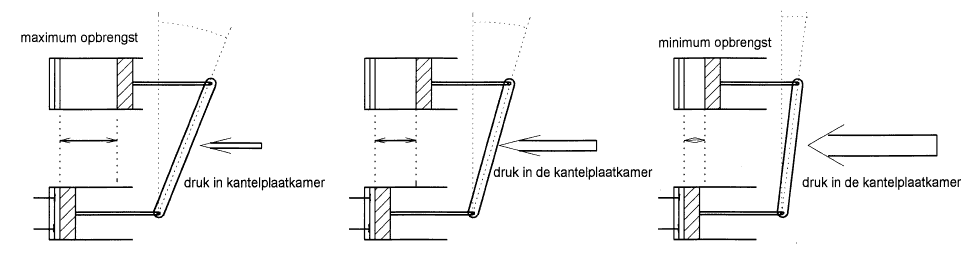
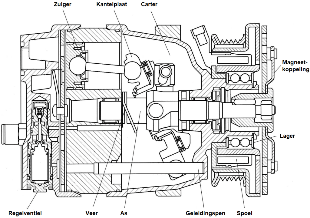
In the illustration we see a line drawing and cross-section of a tilting plate compressor. The piston makes a horizontal stroke, which is determined by the angle of the tilting plate. In this image, the plate is maximally tilted, which means that the piston can make maximum horizontal movement (indicated by the red compression space in the cylinder). In the three drawings (from top to bottom) we see a full pressure stroke of a piston as a result of the rotation of the tilting plate.
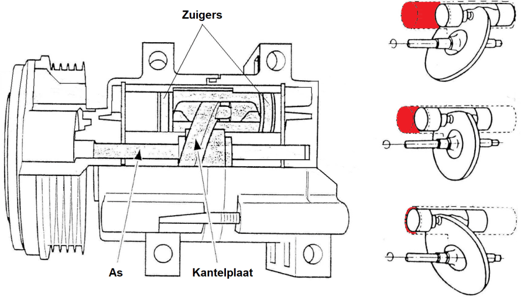
In this situation, the pump delivers the maximum flow because the tilting plate has made a maximum stroke. If a lower yield is desired because the pressure becomes too high and - due to too much refrigerant - freezing phenomena of the evaporator can occur, the magnetic coupling is disconnected in a compressor with a "fixed stroke", so that the compressor is no longer driven. With a compressor with a “variable stroke” the plate is less “tilted”. The angle in which the plate tilts is smaller, so that the stroke of the piston is also smaller. The fixed and variable stroke compressors are described later on the page.
Above each piston are 2 valves attached to a poppet plate spring: the suction valve and the discharge valve. As the piston moves from TDC to ODP, it forces the refrigerant out past the discharge valve and into the high-pressure line to the condenser.
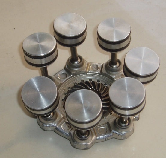
Tilting plate compressors can have between 4 and 8 pistons/plungers and come in two versions: namely the compressor with fixed stroke, and that with variable stroke. These are described below.
Fixed stroke tilt plate compressor:
This compressor is driven by the engine's multi-belt and rotates synchronously with the engine speed (between 600 and 6000 revolutions per minute). The magnetic coupling controls the switching on and off of the compressor, which will be explained further later.
When the compressor is switched on, the rotating tilting plate moves the pistons up and down. Suction and discharge valves at each cylinder allow the pistons to draw in gas and move it under pressure to the high pressure section of the system.
A fixed-stroke compressor moves a fixed volume per revolution. The yield therefore depends on the compressor speed, or the engine speed. To control the output, the compressor is continuously switched on and off: switching on when pressure drops and switching off when the pressure is too high. Particularly with small engines, switching on can be felt as a “shock” due to the required power. The abrupt switch-on causes increased mechanical stress and disrupts the control, resulting in variations in the cooled air temperature for occupants.
If the engine speed is too high and the resulting discharge pressure increases, more refrigerant will flow through the evaporator. This slows down cooling and can freeze the evaporator. In such cases, the magnetic coupling switches off thanks to the thermostat or pressure switch.
Tilting plate compressor with variable stroke:
With this type of compressor, the angle of the tilting plate is adjustable thanks to an adjustment device. By setting the tilt plate as straight as possible, the stroke of the pistons is limited and the yield is minimal. On the other hand, by placing the tilting plate as slanted as possible, the pistons make a much larger stroke and the yield increases considerably. We see the following versions of the variable stroke tilting plate compressor:
- with internal regulation and magnetic coupling;
- external control with and without magnetic coupling.
Internal control and magnetic coupling:
The illustration shows how the position of the tilting plate can affect the stroke of the piston. A higher engine speed results in a higher compressor output. This causes a rise in pressure throughout the system, which triggers the adjuster to increase the pressure in the tilt plate chamber.
The increased pressure forces the tilt plate to become more upright, reducing capacity. If the flow decreases, the adjuster closes and the pressure in the tilt plate chamber decreases. This causes the plate to tilt again, allowing the pistons to make a larger stroke. The greater the angle, the greater the stroke and the greater the yield.
An internal (mechanical) control system for adjusting the position of the tilt plate on a variable stroke A/C compressor typically uses the suction pressure to automatically control the adjustment. This system uses a pressure controlled mechanism that responds to changes in compressor suction pressure.
The control mechanism usually consists of one or more diaphragm or bellows chambers that communicate with the suction side of the compressor and with the tilt plate drive shaft. If the suction pressure changes, it causes movement in the diaphragm or bellows. This movement is then transferred to the mechanism that adjusts the tilt plate angle.
- At higher suction pressures, such as when cooling demand increases, the pressure-controlled mechanism will adjust the tilt plate angle. This leads to a longer stroke length of the pistons and thus to a higher compression of the refrigerant. This results in a higher discharge pressure and a larger cooling capacity.
- At lower suction pressures, the mechanism will reduce the tilt plate angle, resulting in shorter piston strokes and lower refrigerant compression. This lowers the discharge pressure and adjusts the cooling capacity to the reduced cooling requirement.
In a variable displacement A/C compressor, a valve controls the connection to the crankcase (in the tilting disc chamber) and both the high and low pressure sides of the compressor. The pressure on the low pressure side is influenced by the measured suction pressure. The following explains how the control valve works when the flow is increased and decreased.
Increase Yield:
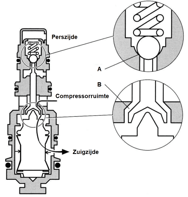
With decreasing cooling capacity, the temperature on the suction side rises and the suction pressure increases. This suction pressure causes the elastic bellows to compress, making it smaller. When the bellows are compressed, ball valve A closes and valve B opens. This creates a connection to the crankcase. This allows the pressure in the tilting disc chamber to escape to the low pressure side (on the suction side), causing the tilting disc to be more inclined. This results in a higher output of the compressor and an increase in cooling capacity.
Reduce Yield:
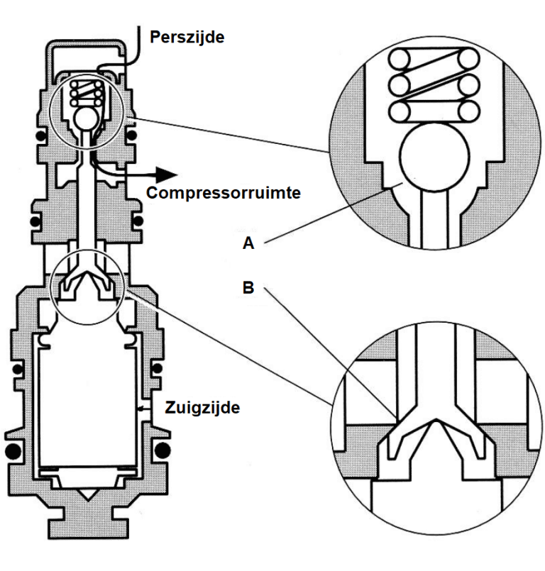
As the cooling capacity increases, the suction pressure decreases. The suction pressure decreases and the bellows expands in volume, closing orifice B and opening ball valve A. This causes high pressure gas to enter and through ball valve A and the orifice to the tilting disc housing. This causes the tilting disc to stand upright. As a result, the pump output decreases and the cooling capacity becomes smaller.
The control valve adjusts the pressure in the tilting disc chamber. The resulting pressure difference with respect to the pressure in the compression chambers leads to a tilting of the tilting disc, which affects the output of the pump. The stroke size is controlled by the pressure in the low pressure section of the air conditioning system. Variable stroke (output) compressors usually do not have a thermostat switch on the evaporator. The inlet pressure is kept at 2 bar with these compressors.
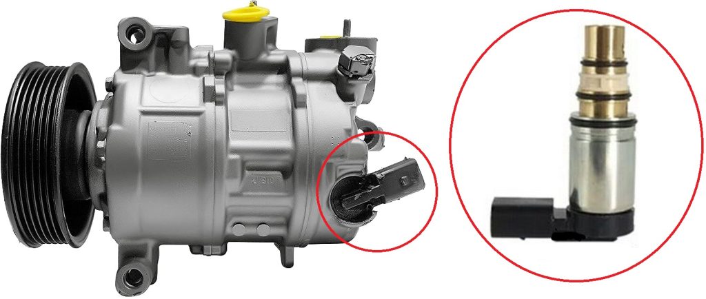
External control, without magnetic coupling:
In a compressor with external control, a solenoid valve is used to control the pressure in the compressor housing. The solenoid valve is controlled by an ECU (the engine ECU or air conditioning ECU) by means of a PWM signal. However, the suction pressure continues to play a role in the control process. The A/C ECU receives signals such as the desired A/C mode (dehumidify, cool), the target and actual temperature, and the outdoor temperature.
Based on this, the computer calculates the optimum setting for the control valve and thus the compressor output. If necessary, the suction pressure can also vary. Practically speaking, the suction pressure varies between 1,0 and 3,5 bar. Low suction pressure improves cooling capacity at low compressor speed. A higher than average suction pressure at low heat load results in more efficient operation and therefore lower fuel consumption. The heavy magnetic coupling can now be omitted, which saves approximately 1 kg. Usually the clutch is equipped with a vibration damper and a slip mechanism.
An increased control current to the control valve closes the passage from the high pressure chamber to the crankcase. The variable opening provides space for the pressure-increasing leakage gas to be discharged via the suction pressure chamber. This equalizes the crankcase pressure (Pc) and the suction pressure Ps, putting the swash plate in the maximum flow position.
Reducing the yield is done by increasing the pressure in the crankcase. The control valve opens, creating the connection between crankcase and high pressure chamber. The control valve has a bellows actuated by the suction pressure, which changes the set point. The control current to the control valve works together with the bellows setting. A small variable orifice allows a limited flow of refrigerant to the suction pressure chamber.
Lubrication of the compressor:
Moving parts always generate heat, which is why they must be lubricated. In addition to its lubricating properties, the oil also provides sealing and sound dampening. In the beginning the compressor is filled with oil, and lubrication is realized through a mist lubrication. This oil mist also reaches the plungers and is then carried along with the refrigerant throughout the system. During condensation, a mixture of refrigerant and a liquid oil mist forms. This oil mist is again sucked in by the compressor.
The synthetic oil PAG (Polyalkylene glycol) is specially designed for the refrigerant R134a and must never be replaced by another type of oil. However, one must take into account the different viscosities prescribed by manufacturers. Consult the specifications for this.
Common PAG oils are:
- PAG 46 (lowest viscosity)
- PAGE 100
- PAG 150 (highest viscosity)
- PAG oil with the addition of YF for use with the refrigerant R1234YF, due to the sensitivity to moisture in the system.
In addition to PAG oils, there are also mineral, PAO and POE oils.
- Mineral oil was used in the old R12 systems.
- PAO oil (PolyAlphaOlefin) is fully synthetic and non-hygroscopic. This is in contrast to PAG oil, which is highly hygroscopic.
- POE oil (Polyester) is used in electric air conditioning compressors of HV vehicles. If the wrong oil (PAG) is used, the insulated coating of the copper wire of the electric motor will be affected.
When mounting a new compressor, there is already oil (about 200 to 300 ml) in the compressor. The manufacturer specifies this oil quantity in the documentation.
It is difficult to determine how much refrigerant and oil are present in the system without draining the system. In the event of a repair, for example after replacing a condenser, a small amount of oil will be lost. The manufacturer usually specifies the distribution in the system. In general, we can stick to this distribution:
• compressor approx. 50%
• condenser approx. 10%
• flexible suction line approx. 10%
• evaporator approx. 20%
• filter/dryer approx. 10%
When the system is turned on for the first time, the oil is distributed throughout the system. If the system is later drained and then refilled, for example when replacing another part or during maintenance, the oil can be added to the refrigerant via the charging station. It is essential to ensure that too much oil does not enter the compressor. The result of too much oil in the system may be that the compressor creates a liquid hammer. In air conditioning systems with a capillary tube, an accumulator is mounted just before the compressor, which constantly adjusts the amount of oil to the amount of refrigerant (see the page about the accumulator).
Magnetic coupling:
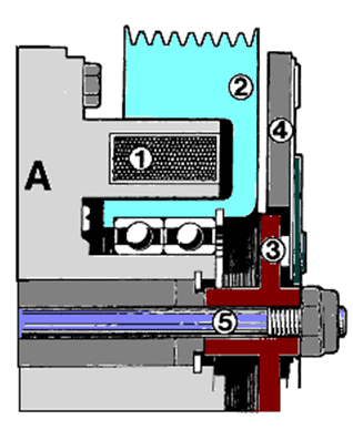
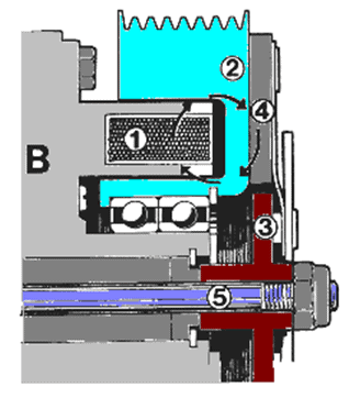
The pulley of the air conditioning pump is continuously driven by the multi-belt. On fixed-stroke and some variable-stroke tilt-plate compressors, the magnetic clutch controls the on and off of the A/C compressor. When the compressor is switched on, an electromagnet (1) in the coupling is activated. This causes the magnet to attract the spring-mounted clutch disc (4), creating a firm connection between the pulley and the pump. When the air conditioner is turned off, the electromagnet is no longer activated and its magnetic action stops. The spring of the clutch disc pushes it away from the pump. The pulley now continues to rotate with the multi-belt, while the pump (internal) is stationary.
Turning on the air conditioning is most beneficial when the engine is running at low revs, such as with the clutch depressed or when the engine is idling. This minimizes wear on the magnetic coupling. For example, if the air conditioning is turned on at 4500 rpm, the solenoid will activate the clutch and there will be a large difference in speed between the stationary pump and the rotating pulley. This can cause slippage, which leads to increased wear.
Sounds:
A few characteristic sounds may occur:
Clapping sound when switching on: A loud rattling sound when the compressor is switched on may indicate a possible adjustment of the magnetic coupling. According to the type of compressor, this adjustment can reduce the air gap and minimize noise.
Humming noise from the air conditioning pump: A humming sound indicates a fault in the pump or possibly a lack of refrigerant and oil in the system. Consult an air conditioning specialist to check, drain and refill the system with the correct amount of refrigerant and oil.
Flapping noise from the air conditioning pump: A chattering sound can also indicate a pump failure. Check that the magnetic coupling is firmly attached to the pump to prevent loosening of the center bolt.
Buzzing sound linked to engine speed: A humming sound that can be heard in the cabin and changes with engine speed indicates resonance or vibration. This can be caused by a too low refrigerant charge or by air conditioning pipes that resonate. If the refrigerant level is OK, a pipe causing vibration can be identified by holding while accelerating. Special vibration dampers, such as those available for specific problems such as MINI, can correct this type of vibration.
Related page: